

Drawings and documents
USPTO scan
The patent as scanned by the USPTO
-
 Page 1
-
 Page 2
-
 Page 3
-
 Page 4
-
 Page 5
-
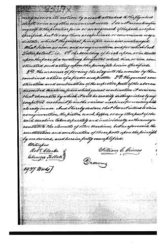 Page 6


U.S. Patent and Trademark Office · Google Patents
Published accounts: specification
Specification printed in the Journal of the Franklin Institute
Journal of the Franklin Institute, new ser., vol. 16 (1835), p. 38 · View the page
Text of the specification as printed in the Journal, from OCR; not proofread.
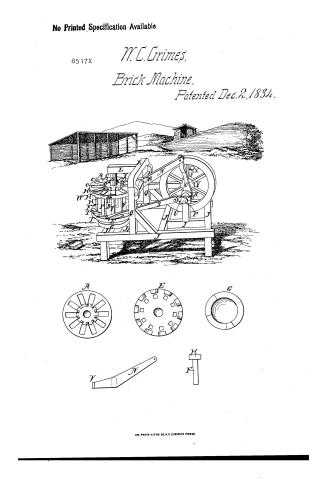
Specification of a Patent for a Machine for Pressing Bricks. Granted to WILLIAM C. GRIMES, of York, York county, Pennsylvania, December 2nd, 1834. The general principle of the construction and operation of this machine, is briefly as follows. Upon a vertical shaft, or spindle, is fixed a wheel, disk, or rim, of sufficient size, which is to revolve horizontally. In the upper face of this wheel are a number of holes, or mortises, which are the moulds in which the bricks are to be pressed. The bottoms of these GRIMES' Machine for Pressing Bricks. moulds are not a fixed portion of the moulding wheel, but are the upper faces of movable pistons, that slide up and down in the moulds, as the wheel revolves. The rods, or posts, which support and guide the pistons, descending vertically from them. The lower ends of the piston rods, or posts, slide round as the wheel revolves, upon a circular horizontal platform, or rim, or rather upon two platforms, one-half of the circle, or thereabouts, being elevated above the other about two or three inches. When the pistons rest upon this elevated portion of the circular rim, or platform, their upper faces are flush with, or above, the upper surface of the wheel; hence the bricks which have been pressed, being thus raised, can be removed with facility; while upon the opposite side of the wheel, the pistons upon the lower portion of the rim, have their upper surfaces sunk down within the moulds, leaving cavities into which the bricks are dropped, as the pistons are depressed, the motion of the wheel, which is intermitting, not being too rapid for that purpose. Just before the pistons rise on to the elevated portion of the circular rim, they pass under the short end of a strong iron lever, which projects over the face of the horizontal moulding wheel, far enough to cover the moulds as they pass under it. The lever receives a continuous motion from a crank and shackle bar, the latter being jointed to the opposite, or long end, of the lever. The crank is regulated and assisted by a heavy fly-wheel, in passing that point in which there is the greatest resistance to its motion. While a brick is being pressed by the short end of the lever, the moulding wheel is at rest, as it receives its motion by a pall, or movable hand, that has a vibratory or reciprocating motion, which it receives from a crank fixed for that purpose, on to the end of the flywheel shaft. The horizontal moulding wheel may be of iron, and cast in one entire piece, of such thickness as may be necessary to its strength, the requisite depth of the moulds being formed by a flanch, rim, or projection, standing out upon the face of the wheel, the said rim, or flanch, making the sides and ends of the moulds. The moulds being in a circle, are placed as near to the periphery of the wheel as a proper thickness of metal will allow; the inner ends of the moulds may approach very near to each other, leaving only sufficient strength of metal between them; hence it may be seen that the number of moulds in the face of the wheel will depend entirely upon its diameter, which may be very much varied, but from three to six feet I think the most suitable. The moulding wheel, pistons, horizontal rim, and fly wheel, should consist of cast iron, and, in fact, the whole machine should be made of metal. Motion may be given to the machine by a strap, carried round the fly-wheel, or by the crank attached to the end of the fly-wheel shaft, which may project beyond its bearing for that purpose. I do not mean to confine myself to the particular form and arrangement of the parts as before specified, but to vary them as experience or convenience may dictate, whilst the general principle remains unchanged. RIDGWAY'S Improved Smelting Furnace. What I claim as new, and as my invention, in the above described machine for pressing brick, and for which I ask letters patent, is1st. The revolving horizontal wheel of moulds, constructed in the manner, or upon the principle, herein described, in which the processes of putting in, pressing, and removing the bricks from the moulds, are all done at one and the same time. 2d. I also claim the revolving pistons, as connected with the revolving moulds, and operating in the manner, or upon the principle, set forth in the foregoing specification. 3d. I also claim the employment of the stationary rim with a double platform, for raising and depressing the pistons, as before described. 4th. I also claim the scolloped rim, or flanch, for the purposes hereinbefore set forth. 5th. I also claim the pressing of brick by means of a lever, operating, and operated upon, as herein shown. 6th. I also claim the general construction and combination of the respective parts of the above described machine, from which general combination it derives that character by which any competent machinist will readily distinguish it from any of the brick pressing machines previously in use. But I do not claim the pistons, fly-wheel, shafts, or any other part, taken individually, as these may constitute the elements of other machines; but, as aforesaid, the construction and combination of these parts upon the principle by me devised, and herein fully exemplified. WILLIAM C. GRIMES. Abstract of a
Published accounts: journal notice
Notice in the monthly list of patents, with remarks
Journal of the Franklin Institute, new ser., vol. 16 (1835), p. 17 · View the page
5. For a machine for Moulding Brick; William C. Grimes, York, York county, Pennsylvania, December 2.
Remarks. (See the specification.)
Published accounts: journal notice
Notice in the monthly list of patents, with remarks
Journal of the Franklin Institute, new ser., vol. 16 (1835), p. 36 · View the page
A vertical shaft is to be turned by a horse attached to a lever, or sweep; upon this vertical shaft there is to be a cog wheel, mashing into a pinion on a second vertical shaft, on the lower end of which there is a bevil wheel taking into a pinion on a horizontal shaft, passing under the feet of the horse, and from which motion is to be communicated, in the usual way, to a thrashing, or other machine. The patentee gives the precise proportions of the respective parts, and says that what he claims as his "invention and improvement, is the proportions and peculiar arrangement of the several parts of the above described horse power." Now, as regards arrangement, there is nothing peculiar, and as respects proportion, the law declares, "that simply changing the form, or proportions, of any machine, in any degree, shall not be deemed a discovery." SPECIFICATIONS OF AMERICAN PATENTS. Abstract of the Specification of a Patent for a Machine for Moulding Bricks. Granted to WILLIAM C. GRIMES, of York, in the county of York, in the State of Pennsylvania, December 2nd, 1834.
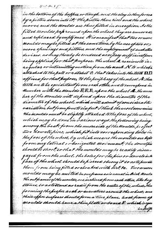
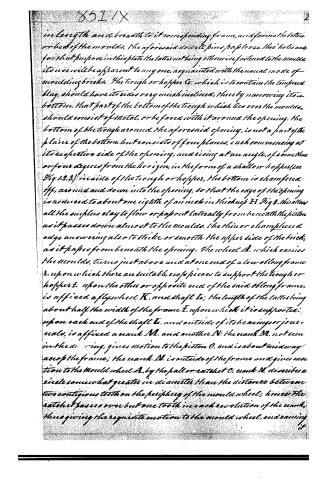
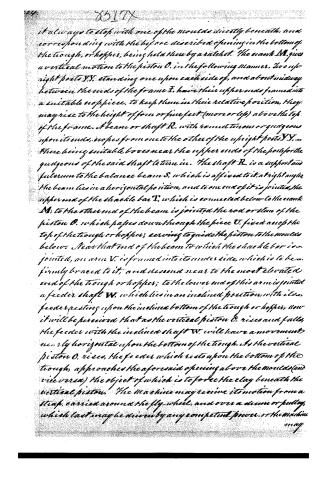
Remarks. This machine is constructed upon the following general principles. A wheel is affixed horizontally to, and revolves with, an upright shaft, the latter being properly supported above and below by a suitable step and box, in which its gudgeons turn. The moulds in which the bricks are to be formed, are placed around and upon the face, or upper side, of the wheel, near its periphery; these may stand in the direction of radii from the centre of the wheel, or otherwise. Two or more moulds may be united or connected together. A hopper, or trough, of sufficient capacity, is placed in an inclined position, with its lower end over one or more of the moulds at a time, as they pass under it. This hopper is to contain the tempered clay of which the bricks are to be made, and through that part of the bottom of it which projects over the mould, or moulds, an opening, or openings, are made of the length and width of a brick, through which the clay is to descend into the moulds. The motion of the wheels is not to be continuous, but intermitting; while it is at rest, a mould is immediately beneath the opening in the bottom of the hopper, or trough, and the clay is then forced by a piston down into it; the piston then rises, and the wheel moves, and the moulds are thus filled in succession. As the filled moulds pass round upon the wheel, they are removed, and replaced by empty ones. It is manifest that two or more moulds may be filled at the same time, by the use of two or more openings and pistons, and the employment of such other devices as may thereby be rendered necessary, sufficient power being applied for that purpose. The number of moulds will depend upon the diameter of the wheel, which will admit of considerable variation, but from four to six feet I think the most convenient. The moulds must be slightly attached to the face of the wheel, which may be done in various ways, the following being among the best. From the under side of the m moulds project two dowel pins, which fit into corresponding holes in the face of the wheel, by which means the moulds are kept from any lateral or horizontal movement. The dowel pins should be short, so that the moulds may be readily disengaged from the wheel. The holes for the pins, or dowels, in the face of the wheel, should be pierced through it, so as to prevent them from being filled, or choked with dirt, &c. Two or more moulds may be united in one frame, as is usual in brick moulds. The frames of the moulds are inclined from each other, like key-stones, so as to stand as radii from the centre of the wheel, thus forming the proper arch or curvature around the wheel, and their upper surfaces should form a true plane. Each frame of moulds has a thin plate, or board, which is equal in length and breadth to its corresponding frame, and forms the bottom or bed of GRIMES' Machine for Pressing Bricks. the moulds. The aforesaid dowel pins pass loosely through holes made for the purpose in this plate; the latter not being otherwise fastened to the moulds, its use will be apparent to any one acquainted with the usual mode of moulding bricks. 'The machine may receive its motion by a strap, carried around the fly-wheel, and over a drum, or pulley, which last may be driven by any competent power; or the machine may receive its motion by a crank attached to the fly-wheel shaft, or in any other convenient mode. I do not mean to confine myself to the particular form or arrangement of the parts as before specified, but to vary them as experience or convenience may dictate, whilst the general principle remains unchanged. What I claim as new, and as my invention, and for which I ask letters patent, is, 1st. The moulding of brick upon, or in moulds upon, the face of a revolving horizontal wheel, disk, or rim, constructed and acting upon the principle herein specified. 2d. The manner of forcing the clay into the moulds, by the combined action of a feeder and piston. 3d. The general construction and combination of the respective parts of the above described machine, from which general combination it derives that character by which it will be readily distinguished, by any competent machinist, from the various machines for moulding bricks already in use.
Published accounts: journal notice
Notice in the monthly list of patents, with remarks
Journal of the Franklin Institute, new ser., vol. 16 (1835), p. 38 · View the page
And I do hereby declare that I do not intend to claim as my invention, the piston, cranks, hopper, or any other part of the said machine, taken separately and individually, as these may constitute the elements of other machines; but, as aforesaid, the construction and combination of these parts upon the principle by me devised, and herein fully exemplified. WILLIAM C. GRIMES. The foregoing comprises about one-half of the specification, the remainder generally referring to the drawings. The same remark will apply to the next patent, and also to those for making nails. The machines manifest much ingenuity, and an account of their performance, when completed, has been promised, which, if satisfactory, will appear in the Journal.-[Editor. Abstract of the Specification of a Patent for a Machine for Pressing Bricks. Granted to WILLIAM C. GRIMES, of York, York county, Pennsylvania, December 2nd, 1834.
Remarks. The general principle of the construction and operation of this machine, is briefly as follows. Upon a vertical shaft, or spindle, is fixed a wheel, disk, or rim, of sufficient size, which is to revolve horizontally. In the upper face of this wheel are a number of holes, or mortises, which are the moulds in which the bricks are to be pressed. The bottoms of these GRIMES' Machine for Pressing Bricks. moulds are not a fixed portion of the moulding wheel, but are the upper faces of movable pistons, that slide up and down in the moulds, as the wheel revolves. The rods, or posts, which support and guide the pistons, descending vertically from them. The lower ends of the piston rods, or posts, slide round as the wheel revolves, upon a circular horizontal platform, or rim, or rather upon two platforms, one-half of the circle, or thereabouts, being elevated above the other about two or three inches. When the pistons rest upon this elevated portion of the circular rim, or platform, their upper faces are flush with, or above, the upper surface of the wheel; hence the bricks which have been pressed, being thus raised, can be removed with facility; while upon the opposite side of the wheel, the pistons upon the lower portion of the rim, have their upper surfaces sunk down within the moulds, leaving cavities into which the bricks are dropped, as the pistons are depressed, the motion of the wheel, which is intermitting, not being too rapid for that purpose. Just before the pistons rise on to the elevated portion of the circular rim, they pass under the short end of a strong iron lever, which projects over the face of the horizontal moulding wheel, far enough to cover the moulds as they pass under it. The lever receives a continuous motion from a crank and shackle bar, the latter being jointed to the opposite, or long end, of the lever. The crank is regulated and assisted by a heavy fly-wheel, in passing that point in which there is the greatest resistance to its motion. While a brick is being pressed by the short end of the lever, the moulding wheel is at rest, as it receives its motion by a pall, or movable hand, that has a vibratory or reciprocating motion, which it receives from a crank fixed for that purpose, on to the end of the flywheel shaft. The horizontal moulding wheel may be of iron, and cast in one entire piece, of such thickness as may be necessary to its strength, the requisite depth of the moulds being formed by a flanch, rim, or projection, standing out upon the face of the wheel, the said rim, or flanch, making the sides and ends of the moulds. The moulds being in a circle, are placed as near to the periphery of the wheel as a proper thickness of metal will allow; the inner ends of the moulds may approach very near to each other, leaving only sufficient strength of metal between them; hence it may be seen that the number of moulds in the face of the wheel will depend entirely upon its diameter, which may be very much varied, but from three to six feet I think the most suitable. The moulding wheel, pistons, horizontal rim, and fly wheel, should consist of cast iron, and, in fact, the whole machine should be made of metal. Motion may be given to the machine by a strap, carried round the fly-wheel, or by the crank attached to the end of the fly-wheel shaft, which may project beyond its bearing for that purpose. I do not mean to confine myself to the particular form and arrangement of the parts as before specified, but to vary them as experience or convenience may dictate, whilst the general principle remains unchanged. RIDGWAY'S Improved Smelting Furnace. What I claim as new, and as my invention, in the above described machine for pressing brick, and for which I ask letters patent, is1st. The revolving horizontal wheel of moulds, constructed in the manner, or upon the principle, herein described, in which the processes of putting in, pressing, and removing the bricks from the moulds, are all done at one and the same time. 2d. I also claim the revolving pistons, as connected with the revolving moulds, and operating in the manner, or upon the principle, set forth in the foregoing specification. 3d. I also claim the employment of the stationary rim with a double platform, for raising and depressing the pistons, as before described. 4th. I also claim the scolloped rim, or flanch, for the purposes hereinbefore set forth. 5th. I also claim the pressing of brick by means of a lever, operating, and operated upon, as herein shown.
About this record
- Patentee
- the Journal of the Franklin Institute, Journal
- Date
- the Name and Date index of patents, USPTO records, Jim Shaw's X-patent list
- Invention
- the Name and Date index of patents
- Listed in
- the Name and Date index of patents, USPTO records, Jim Shaw's X-patent list, the Journal of the Franklin Institute, Burke's List of Patents (1847)
- The patentee's full name comes from the Franklin Institute's journal.
- in_burke