

Drawings and documents
National Archives restored drawings: drawing
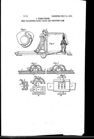
J. Kirkpatrick's Patent Drawing for a Self-balancing Side Valve and Cam

National Archives, Restored Patent Drawings (Record Group 241) · Full-size scan at the National Archives · Catalog record
Text on the drawing
Words on the drawing as machine-read by the National Archives; not checked. Useful mainly for searching.
$125 Slide Valves It Eug. / 136. VALVES. / [152] Balanced. / J KIRKPATRICK'S o / CLASSI NOATION / shifting / 8303-X / LIVICION. / lelf balancing slide Valve and Cam. / Add pet / Patented July 10th 1834. / (voc. 19 h445 of Restored Sape / Shifting Cam / NED / MASSACHUSETTS / 000 / MA bellow tom of Us. de / and / for / plate / Sleem ste Vehifying of / of / model eccentive / bolve / Stomhike / 56am / Tribe / sterm
USPTO scan
The patent as scanned by the USPTO
-
 Page 1
-
 Page 2
-
 Page 3
-
 Page 4


U.S. Patent and Trademark Office · Google Patents
Published accounts: specification
Specification printed in the Journal of the Franklin Institute
Journal of the Franklin Institute, new ser., vol. 14 (1834), p. 203 · View the page
Text of the specification as printed in the Journal, from OCR; not proofread.
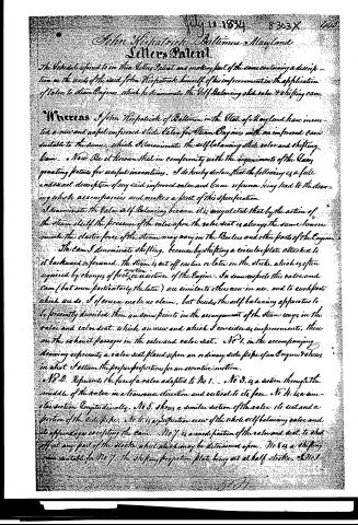
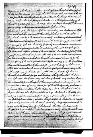
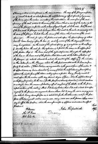
Specification of a patent for an improvement in the application of Valves to Steam Engines. Granted to JOHN KIRKPATRICK, city of Baltimore July –, 1834. Whereas I, John Kirkpatrick, of Baltimore, in the state of Maryland, have invented a new and improved slide valve for steam engines, with an improved cam suitable to the same, which I denominate the Self-balancing Slide Valve, and Shifting Cam; now be it known, that in conformity with the requirements of the law granting patents for useful inventions, I do hereby declare that the following is a full and exact description of my said improved valve and cam, reference being had to the drawing which accompanies, and makes a part of this description. I denominate this valve self-balancing, because it is so regulated that by the action of the steam itself, the pressure of the slide upon the valve seat, is always so regulated as to be the same, however much the elastic force of the steam may vary in the boilers, and other parts of the engine. The cam I denominate shifting, because by shifting a circular plate attached to it, backward or forward, the steam is cut off earlier or later in the stroke, which is often required by_changes of fuel, or resistance of the engine. In some respects, this valve and cam, but more especially the latter, are similar to others now in use, and to such parts which are so, I, of course, make no claim; but, besides the self-balancing apparatus, to be presently described, there are some points in the arrangement of the steam ways, in the valve, and valve seat, which are new and which I consider as improvements. No. 1, in the accompanying drawing, represents a valve seat, placed upon the ordinary side pipe of an engine, and shown in what I esteem the proper proportions for an eccentric motion. No. 2 represents the face of the slide which is adapted to No. 1. No. 3 is a section through the middle of the slide in a transverse direction, and vertical to its face. No. 4 is a similar section, longitudinally. No. 5 shows a similar section of the valve, its seat, and a portion of the side pipe. No. 6 is a perspective view of the whole self-balancing valve, and its appendages, excepting the cam. No. 7 is a modificaKIRKPATRICK'S Improved Steam Valve. tion of the valve and seat, to shut off at any part of the stroke which may be determined upon. No. 8 is a shifting cam suitable for No. 7, the shifting projection plate being set at half stroke. n 4 3. e N1 C d 2 f C ac f C a C 8. f ㅁㅁㅁ b m 6. 2 n 5. C C 9 f In No. 1 the opening a is for the admission of steam into the cylinder, through the steam pipe b. The two parallel openings c care for the alternate admission and escape of steam to and from the two ends of the cylinder, being conducted into them through the cavity in the valve a, and from them in the slide, by the passages in the valve cc, to the longitudinal cavity d, thence to the longitudinal passage in the seat d, thence out through the escape pipe e. The corresponding openings in the valve and seat, are designated by the same letters. The openings acc of the seat, are all of the same dimensions. The opening dis of the same width with them, and in length equal to the width of the three, and the spaces between them. In the valve No. 2, the centre opening, or cavity, a, which may be denominated the steam chest, must be sufficiently wide to embrace the centre opening a, and one of the end openings, c, of the seat. In sliding, therefore, by means of a cam or eccentric motion, the steam will be alternately admitted into, and discharged from, each end of the cylinder ff, through the different openings of the valve and seat. For shutting off at half stroke, or at any other desired point, the KIRKPATRICK'S Improved Steam Valve. construction of the valve is the same as that already described, but there is a difference in the proportion of the openings and spaces. In No. 7, the middle opening of the seat is of double the width of the two end ones c c. The spaces between them are of the same width with the middle opening, and the cavity e of the valve, or steam chest, extends from the centre of the middle opening to the extreme edge of either of the end openings, or the centre opening of the seat may be rather less than twice the width of one of the end openings, and the spaces rather less than that: the proportions of the valve will of course vary with that of the seat. Every competent engineer will readily perceive the effect of this arrangement, and how it may be varied and adapted to shut off at any desired part of the stroke, by moving backward, or forward, the circular plate S, of the shifting cam No. 8. The dotted line shows the form of the cam when the plate is shifted on to w. In No. 6, b is the steam pipe, and g is a cylinder, or chamber, for containing a piston, or plunger, into the lower end of which cylinder steam is admitted through the tube h. The piston rod i, extends up to, and is connected with, the lever j, which has a knife edge or circular fulcrum under the cross piece k of the frame l. The stem m, has a cavity in the upper end to receive the end of the lever; and there is a similar cavity n, in the valve, to receive the lower end of the stem. This mode of forming the joints, although not essential to the general plan, is extremely convenient, as it affords ample bearings, which may be made to move in oil; it also allows the valve to be taken away, without the trouble of turning a screw, and replaced in the same manner. The size of the plunger, or piston, in g, must be such as shall produce the self-balancing effect, operating by means of the lever upon the valve; in making this calculation, the area of one of the end openings of the seat, added to the area of the steam chest, or cavity of the valve, is the area of the plunger, or piston, with a lever of equal length at both ends; but as the end of the lever next the plunger will be longer than that next to the valve, so, inversely, will the area of the plunger be less than the area of the steam chest, and one of the end openings. The nut p upon the piston rod acts upon the spiral spring q, which has its lower bearing upon the bow r, and by means of this, the degree of friction may be regulated. On the inside of the spiral spring q, is a cylinder with a flancht, directly below the nut p; this cylinder is to protect the screw on the upper part of the piston rod i; the lower end of the cylinder passes through the upper part of the bow r; the lower end of the piston rod terminates at the bottom of the hollow of the plunger u, which should be about the centre of the shifting box v; the vibration is thus taken from the plunger, while the other parts connected with the lever conform freely to its action. What I claim as my invention is the general form of the valve, and its appurtenances, as herein described, by means of which the selfbalancing principle is applied, the elastic force of the steam acting upon a piston, being thereby made to react upon the valve with any desired degree of force; also the application of a shifting projection MILLER'S Manufacture of Candles. to the cam (for purposes already described,) which combines in a single cam, the means of shutting off at any part of the stroke, with the principal motion of the valve. And I do hereby declare that I do not intend to confine myself to the precise arrangement herein shown, but to vary the same in any mannnr which I may deem proper, whilst the same principle is applied, and a similar effect produced. JOHN KIRKPATRICK. ENGLISH PATENTS.
Published accounts: journal notice
Notice in the monthly list of patents
Journal of the Franklin Institute, new ser., vol. 15 (1835), p. 97 · View the page
13. For a Self-balancing Slide Valve for Steam Engines; John Kirkpatrick, city of Baltimore, July 10.
About this record
- Patentee
- DATAMP
- Date
- the Name and Date index of patents, DATAMP, USPTO records
- Invention
- DATAMP
- Listed in
- the Name and Date index of patents, DATAMP, USPTO records, Jim Shaw's X-patent list, the Journal of the Franklin Institute, Burke's List of Patents (1847)
- in_burke