

Drawings and documents
National Archives restored drawings: drawing
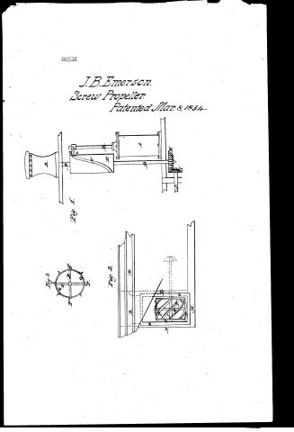
John B. Emerson's Patent Drawing for a Steam Engine and Propulsion Thereby

National Archives, Restored Patent Drawings (Record Group 241) · Full-size scan at the National Archives · Catalog record
Text on the drawing
Words on the drawing as machine-read by the National Archives; not checked. Useful mainly for searching.
CLASS 115.-MARINE PROPULSION / SCIEN PROPELLERS / Fitting and Driving. / Fig. 1, represents the Iteam bylinder, the / #2 thembing / Grooved bylinder and the Capstan. / CLASSIFICATION / A, Heam bylinder B piston rod / 8053.X / John B. Emerson Steam Engine, and / C, section of the cross head, the guides and other / NOISIAIT / Propelling thereby, / parts not being shown. D, thatt carrying / Patented 8 Mar: 1834. / E, a cylinder F groove in the cylinder E. / G, a pm attached to the cross head, carrying a / friction roller a, at its outer end that is receive / sed into the groove, F. H, bevel. wheel on the / lower end of the shaft D. I, bevel prnson / J, shaft of a paddle wheel. K, capstan at / -tached to the upper end D', of the shaft D. / Fig.2 represents the paddle wheel and / fig.3, a cross section of it through its middle. / K, K, part of the stern of a vessel. / I. stern post M, keel, extending aft to rein / ceive an upright post, N, to sustain the outer / end of the paddle wheel shaft J. 0,0, a the / be raised out of the water when its shaft is / ding frame, by which the paddle wheel may / uncoupled. P P spiral propellers. Q.Q, / hoops by which they are sustained. / RR, / arms, which are flat, and are twisted Ipra / rally to support the hoops and aid in the / propelling. / :-: / 7ig:1 / City of Washington / Is / District of Columbia / Fig:2. 2. / On this twenty seventh day of March, 1844, before the subscri / ber, Justice of orlgans the Peace mp and for said bity Solemn personally oath appeared John B. Emerson, of / the Bity of New in the Hate of New any ^ that he is the inventor of certain / ments in the Heam to Engine and in propelling thereby for which decttors Patent of the United / and / is as he verify believes, a true deliveation of the invention described in the Said Letters Patent. / States were granted him, dated the eighth of March 1834, and that the annesed drawing / the lind Your de an (Glean Louenaun Imade Solem out) / intertine please to lathing the balt / P Fig:3. / V.l.Dinn I.P. Leal
USPTO scan
The patent as scanned by the USPTO
-
 Page 1
-
 Page 2
-
 Page 3
-
 Page 4
-
 Page 5


U.S. Patent and Trademark Office · Google Patents
Published accounts: specification
Specification printed in the Journal of the Franklin Institute
Journal of the Franklin Institute, new ser., vol. 14 (1834), p. 262 · View the page
Text of the specification as printed in the Journal, from OCR; not proofread.
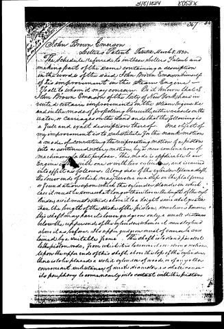
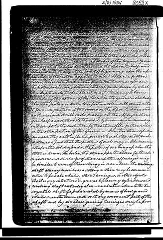
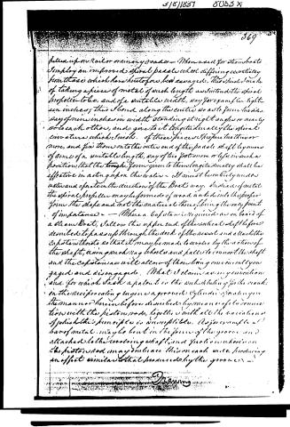
Specification of a Patent for Improvements in the Steam Engine, and the mode of propelling therewith. Granted to JOHN BROWN EMERSON, city of New York, March 8, 1834. To all whom it may concern, be it known, that I, John Brown Emerson, of the city of New York, have invented certain improvements in the steam engine, and in the mode of propelling therewith, either vessels on the water, or carriages on the land, and that the following is a full and exact description thereof. One object of my improvement is to substitute for the crank motion a mode of converting the reciprocating motion of a piston into a continued rotary motion, by a new combination of machinery for that purpose. This mode is applicable to an engine either with one or two cylinders, and is carried into effect as follows:-Along side of the cylinder I place a shaft, the lower end of which may revolve in a step on the platform, or foundation upon which the cylinder stands; in which case it must be somewhat longer than twice the length of the cylinder, as it must extend above it to a height somewhat greater than the length of the stroke of the piston. Sometimes, however, this shaft may have its lower gudgeon only a small distance below the upper end of the cylinder, whence it must extend above it, as before. Its upper gudgeon must, of course, be sustained by a suitable frame. This shaft is to stand parallel to the piston rod, from which it is to receive its revolving motion. Upon the upper end of this shaft, above the top of the cylinder, there is to be placed a solid cylinder of wood, or of any other convenient substance, of such diameter as shall cause its periphery to come nearly into contact with the piston rod, for its whole length, when the piston is raised. The solid cylinder, above described, is to be made to revolve in the following manner: I make a groove in it which commences in its lower end, and passing spirally, extends half way round it by the time it reaches nearly to the upper end, or to a distance, vertically, equal to the stroke of the engine; from that point it passes down, around the opposite half, and returns into itself at the point of beginning. Upon the upper end of the piston, against its side, I place a friction roller, which is to work in the groove in the solid cylinder, the piston rod rising between parallel guide pieces, by which it is kept in its proper place, and its tendency to turn round by the action of the roller in the groove is checked. When the piston is down, this friction roller will stand in the V formed junction of the grooves on the opposite sides, and as it is raised, it will, in its passage to the upper junction, give half a revolution to the solid cylinder, and in descendEMERSON'S Improvements in the Steam Engine. ing, will complete the revolution by the action of the friction roller on the other portion of the groove. When two steam cylinders are used, they are to be placed parallel to each other, and at such distance apart that the pistons of each may in like manner act upon the solid cylinder, the piston of one being up, when the other is down. The boiler, the steam pipe, the valves for the admission and discharge of steam, and other appendages, may be similar to some of those already in use. From the revolving shaft, already described, a rotary motion may be communicated to paddle wheels, steam carriages, or other objects. As it is my intention, in general, to place my cylinders and revolving shaft vertically, I communicate motion to the horizontal shaft of a paddle wheel by means of bevel geared wheels near the lower end, or at any convenient part of the shaft; and by similar gearing, carriages may be propelled upon rail, or ordinary roads. When used for steam-boats, I employ an improved spiral paddle wheel, differing essentially from those which have heretofore been essayed. This spiral I make, by taking a piece of inetal, of such length as I intend the spiral propeller to be, and of a suitable width, say, for example, eighteen inches; this I bend along the centre, so as to form two sides, say of nine inches in width, standing at right angles, or nearly so, to each other, and give to it, longitudinally, the spiral curvature which I wish. Of these pieces I prepare two, three, or more, and fix them on to the outer end of the paddle shaft, by means of arms of a suitable length, say of two feet, more or less, in such a position that the trough form given to them longitudinally, shall be effective in acting upon the water. It must be entirely under water, and operate in the direction of the boat's way. Instead of metal, the spiral propeller may be formed of wood, worked into the proper form; the shape, and not the material thereof, being the only point of importance. Where a capstan is required, as on board of a steam-boat, I allow the upper end of the vertical shaft before described, to pass up through the deck of the vessel, and attach the capstan thereto, so that it may be made to revolve by the action of the shaft, using such rag wheels and palls to connect the shaft and the capstan, as will allow of their being conveniently engaged and disengaged. What I claim as my invention, and for which I ask a patent, is the substituting for the crank, in the reciprocating engine, a grooved cylinder, operating in the manner hereinbefore described, by means of the piston rod; together with all the variations of which this principle is susceptible. As, for example, a bar of metal may be bent in the form of the groove, and attached to the revolving shaft, and friction wheels on the piston rod may embrace this on each side, producing an effect similar to that produced by the groove. I also claim the spiral propelling wheel, constructed and operating in the manner which I have set forth; and likewise the application of the revolving vertical shaft to the turning of a capstan on the deck of a vessel. Not intending, in either of these parts, to confine myself to precise forms or dimensions, but to vary them in such manner as BARTON'S Improvements in Combining Bells. experience or convenience may dictate, whilst the principle of action remains unchanged, and similar results are produced by similar means. JOHN B. EMERSON.
Published accounts: journal notice
Notice in the monthly list of patents, with remarks
Journal of the Franklin Institute, new ser., vol. 14 (1834), p. 237 · View the page
18. For an improvement in the Steam Engine; John B. Emerson, city of New York, March 8.
Remarks. (See the specification.)
Published accounts: journal notice
Notice in the monthly list of patents, with remarks
Journal of the Franklin Institute, new ser., vol. 14 (1834), p. 262 · View the page
SPECIFICATIons of American PATENTS. Specification of a Patent for Improvements in the Steam Engine, and the mode of propelling therewith. Granted to JOHN BROWN EMERSON, city of New York, March 8, 1834.
Remarks. To all whom it may concern, be it known, that I, John Brown Emerson, of the city of New York, have invented certain improvements in the steam engine, and in the mode of propelling therewith, either vessels on the water, or carriages on the land, and that the following is a full and exact description thereof. One object of my improvement is to substitute for the crank motion a mode of converting the reciprocating motion of a piston into a continued rotary motion, by a new combination of machinery for that purpose. This mode is applicable to an engine either with one or two cylinders, and is carried into effect as follows:-Along side of the cylinder I place a shaft, the lower end of which may revolve in a step on the platform, or foundation upon which the cylinder stands; in which case it must be somewhat longer than twice the length of the cylinder, as it must extend above it to a height somewhat greater than the length of the stroke of the piston. Sometimes, however, this shaft may have its lower gudgeon only a small distance below the upper end of the cylinder, whence it must extend above it, as before. Its upper gudgeon must, of course, be sustained by a suitable frame. This shaft is to stand parallel to the piston rod, from which it is to receive its revolving motion. Upon the upper end of this shaft, above the top of the cylinder, there is to be placed a solid cylinder of wood, or of any other convenient substance, of such diameter as shall cause its periphery to come nearly into contact with the piston rod, for its whole length, when the piston is raised. The solid cylinder, above described, is to be made to revolve in the following manner: I make a groove in it which commences in its lower end, and passing spirally, extends half way round it by the time it reaches nearly to the upper end, or to a distance, vertically, equal to the stroke of the engine; from that point it passes down, around the opposite half, and returns into itself at the point of beginning. Upon the upper end of the piston, against its side, I place a friction roller, which is to work in the groove in the solid cylinder, the piston rod rising between parallel guide pieces, by which it is kept in its proper place, and its tendency to turn round by the action of the roller in the groove is checked. When the piston is down, this friction roller will stand in the V formed junction of the grooves on the opposite sides, and as it is raised, it will, in its passage to the upper junction, give half a revolution to the solid cylinder, and in descendEMERSON'S Improvements in the Steam Engine. ing, will complete the revolution by the action of the friction roller on the other portion of the groove. When two steam cylinders are used, they are to be placed parallel to each other, and at such distance apart that the pistons of each may in like manner act upon the solid cylinder, the piston of one being up, when the other is down. The boiler, the steam pipe, the valves for the admission and discharge of steam, and other appendages, may be similar to some of those already in use. From the revolving shaft, already described, a rotary motion may be communicated to paddle wheels, steam carriages, or other objects. As it is my intention, in general, to place my cylinders and revolving shaft vertically, I communicate motion to the horizontal shaft of a paddle wheel by means of bevel geared wheels near the lower end, or at any convenient part of the shaft; and by similar gearing, carriages may be propelled upon rail, or ordinary roads. When used for steam-boats, I employ an improved spiral paddle wheel, differing essentially from those which have heretofore been essayed. This spiral I make, by taking a piece of inetal, of such length as I intend the spiral propeller to be, and of a suitable width, say, for example, eighteen inches; this I bend along the centre, so as to form two sides, say of nine inches in width, standing at right angles, or nearly so, to each other, and give to it, longitudinally, the spiral curvature which I wish. Of these pieces I prepare two, three, or more, and fix them on to the outer end of the paddle shaft, by means of arms of a suitable length, say of two feet, more or less, in such a position that the trough form given to them longitudinally, shall be effective in acting upon the water. It must be entirely under water, and operate in the direction of the boat's way. Instead of metal, the spiral propeller may be formed of wood, worked into the proper form; the shape, and not the material thereof, being the only point of importance. Where a capstan is required, as on board of a steam-boat, I allow the upper end of the vertical shaft before described, to pass up through the deck of the vessel, and attach the capstan thereto, so that it may be made to revolve by the action of the shaft, using such rag wheels and palls to connect the shaft and the capstan, as will allow of their being conveniently engaged and disengaged. What I claim as my invention, and for which I ask a patent, is the substituting for the crank, in the reciprocating engine, a grooved cylinder, operating in the manner hereinbefore described, by means of the piston rod; together with all the variations of which this principle is susceptible. As, for example, a bar of metal may be bent in the form of the groove, and attached to the revolving shaft, and friction wheels on the piston rod may embrace this on each side, producing an effect similar to that produced by the groove.
About this record
- Patentee
- DATAMP
- Date
- the Name and Date index of patents, DATAMP, USPTO records
- Invention
- DATAMP
- Listed in
- the Name and Date index of patents, DATAMP, USPTO records, Jim Shaw's X-patent list, the Journal of the Franklin Institute, Burke's List of Patents (1847)
- The Franklin Institute's journal spells the name differently.
- in_burke