

Drawings and documents
USPTO scan
The patent as scanned by the USPTO
-
 Page 1
-
 Page 2
-
 Page 3
-
 Page 4
-
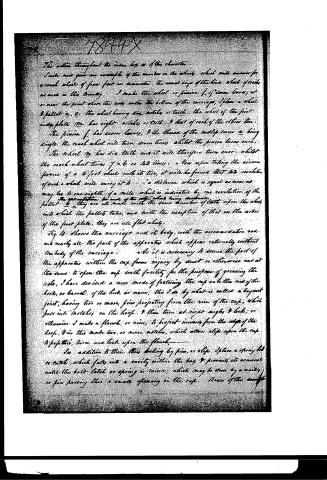 Page 5
-
 Page 6


U.S. Patent and Trademark Office · Google Patents
Published accounts: specification
Specification printed in the Journal of the Franklin Institute
Journal of the Franklin Institute, new ser., vol. 13 (1834), p. 336 · View the page
Text of the specification as printed in the Journal, from OCR; not proofread.
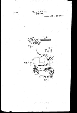
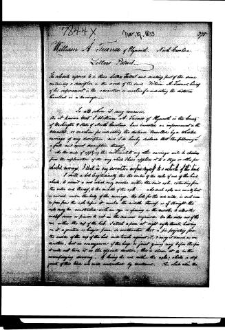
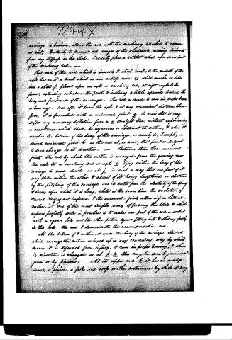
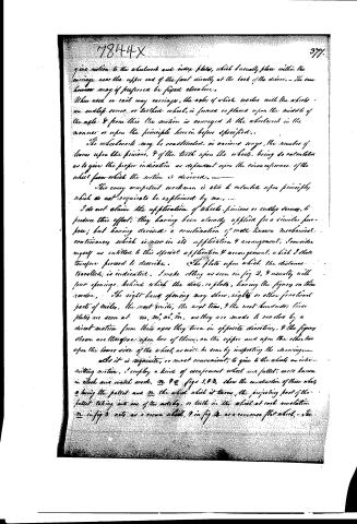
Specification of a patent for an Odometer, or machine for indicating the distance traveled by a Wheeled Carriage. Granted to WILLIAM A. TURNER, Plymouth, Washington county, North Carolina, November 19th, 1833. (WITH A COPPERPLATE.) To all whom it may concern, be it known that I, William A. Turner, of Plymouth, in the county of Washington, and State of North Carolina, have invented an improvement ent in the Odometer, or machine for indicating the distance traveled by a wheeled carriage of any description, and I do hereby declare that the following is a full and exact description thereof. As the mode of applying this instrument to any other carriage will be obvious from the explanation of the way in which I have applied it to a stage, or other four wheeled carriage, I shall in my description confine myself to a vehicle of this kind. I drill a hole, longitudinally, through the centre of the axle of one of the hind wheels, to admit a rod which may revolve within the said axle, extending from the outer end thereof, to the middle of the axle. As such axles are usually bent, or curved, under the body of the carriage, the hole for the rod will, in such case, be free from the axle before it reaches the middle thereof; or, if straight, the axle may be constructed with an eye, or opening, in the middle, to allow the endless screw, or pinion, to act in the manner required. On the outer end of this rod, within the cap of the hub, I attach a piece at right angles thereto, having on it a jointed, or hinged, piece, so constructed that a pin projecting from the inside of the cap of the hub, will touch against it, and carry it round in one direction, but in consequence of the hinge, or joint, giving way before the pin, it will not turn it in the opposite direction; this is shown at a in the accompanying drawing, b being the rod within the axle; clicks, or stop joints, of this kind, are well understood by workmen. This click, when the carriage is backed, allows the rod, with the machinery attached to it, to remain at rest. Entirely to prevent all danger of the wheel work moving backwards from any stiffness in the click, I usually place a ratchet wheel upon some part of the revolving rod. That end of the rod which is inwards, and which reaches to the middle of the axle, has on it a bevel wheel, or an endless screw, e, which mashes, or takes, into a wheel f; placed upon an axle, or revolving rod, at right angles to the former, extending out above the perch, and inclining a little upwards towards the body and front end of the carriage. This rod is made to run in proper boxes, or bearings. Soon after it leaves the axles, and at any convenient distance therefrom, it is furnished with an universal joint, g, in order that it may suffer any necessary deflexion from a straight line, without experiencing a resistance which shall be injurious, or obstruct its motion; and when it reaches the bottom of the body of the carriage, or nearly so, I employ a second universal joint, h, as the rod at or near TURNER'S Odometer. that point is subject to some change in its direction. Between these two universal joints, the rod by which the motion is conveyed from the gearing near the axle, to a revolving rod or axle, i, lying within the body of the carriage, is made double as at j, in such a way that one part of it may slide within the other, and admit of its being lengthened or shortened by the pitching of the carriage, and by its motion from the elasticity of the springs and braces upon which it is hung; whilst at the same time the revolution of the rod itself is not impeded, and the universal joints allow a free lateral motion. One of the most simple modes of forming this slide, and which answers perfectly well in practice, is to make one part of the rod a socket with a square hole, and the other portion square, fitting into and sliding freely in this hole; this rod I denominate the accommodation rod. At the bottom of, and within, or under, the body of the carriage, the rod which conveys the motion is boxed up in any convenient way, by which means it is defended from injury; it runs in proper bearings, and where its direction is changed, as atk k, this may be done by universal joints, or by pinions. At its upper end l, it has an endless screw, a pinion, a fork and cross, or other contrivance by which it may give motion to the wheel work, and index plates which I usually place within the carriage near the upper end of the front, directly at the back of the driver. The same, however, may, if preferred, be fixed elsewhere. When used on rail-way carriages, the axles of which revolve with the wheels, an endless screw, or toothed wheel, is formed, or placed, upon the middle of the axle, and from this, the motion is conveyed to the wheel work, in the manner, or upon the principles, hereinbefore specified. The wheel work may be constructed in various ways; the number of the leaves upon the pinions, and of the teeth upon the wheels, being so calculated as to give the proper indication, as dependent upon the circumference of the wheel from which the motion is derived. This every competent workman is able to calculate, upon principles which do not require to be explained by me. I do not claim the application of wheels, pinions, or endless screws, to produce this effect, they having been already applied for a similar purpose; but having devised a combination of well known mechanical contrivances which is new in its application and arrangement, I consider myself as entitled to this special application and arrangement, which I shall therefore proceed to describe. The plate upon which the distance traveled is indicated, I make oblong, as seen in fig. 2, and usually with four openings, behind which the dials, or plates, having the figures on them, revolve. The right hand opening shows eighths, or the fractional parts of miles, the next units, the next tens, and the next hundreds; these plates are seen at m, m', m", m'''. As they are made to revolve by a direct motion from their axes, they turn in opposite directions, and the figures shown are, therefore, upon two of them on the upper, and upon the other two on the lower, side of the wheel, as will be seen by inspecting the drawing. As it is requisite, or most convenient, to give to the wheels TURNER'S Odometer. an intermitting motion, I employ a kind of escapement wheel and pallet, well known in clock and watch work: n and o, figs. 1 and 3, show the construction of these wheels, o being the pallet, and n the wheel which it turns; the projecting part of the pallet taking into one of the notches, or teeth, in the wheel at each revolution: n in fig. 3 acts as a crown wheel, and in fig. 4 as a common flat wheel. The action throughout the index box is of this character; p,p, p, are spring checks. the use of which is apparent. I will now give an example of the numbers on the wheels which will answer for a coach wheel of five feet in diameter, the usual size of the hind wheels of coaches as used in this country. I make the wheel or pinion f, of seven leaves; at, or near, the point where the rod enters the bottom of the carriage, I place a wheel and pallet n o, the wheel having six notches or teeth; the wheel of the first index plate m, has eight notches or teeth, and those of each of the others ten. The pinion f has seven leaves, and the thread of the endless screw a being single, the coach wheel will turn seven times whilst the pinion turns once. The wheel n has six teeth, and it will turn once, therefore, whilst the coach wheel turns 7×6, or 42 times. Now upon taking the circumference of a five foot wheel, with its tire, it will be found that 42 revolutions of such a wheel will carry it to a distance which is equal, as near as may be, to one-eighth of a mile, which is indicated by one revolution of the pallet l. The calculation for each of the other wheels being decimal, they are all made with the same number of teeth upon the wheels into which the pallets take, and with the exception of that on the arbor of the first plate, they are all flat wheels. Fig. 4, shows the carriage and its body, with the accommodation rod, and nearly all the parts of the apparatus which appear externally, without the body of the carriage. As it is necessary to secure the part of the apparatus within the cap from injury by dust, or otherwise, and at the same time to be able to open the cap with facility for the purpose of greasing the axle, I have devised a new mode of fastening the cap on to the end of the hoop, or barrel, of the hub, or nave; this I do by what is called a bayonet joint, having two or more pins projecting from the rim of the cap, which pass into notches on the hoop, and then turn at right angles, and lock; or otherwise I make a flanch, or rim, to project inwards from the edge of the hoop, and in this make two or more notches, which allow clips upon the cap to pass through, turn, and lock upon the flanch. In addition to their thus locking by pins, or clips, I place a spring bolt, or catch, which falls into a cavity within the box, and prevents its removal until the bolt, latch, or spring, is raised; which may be done by a nail or pin, passing through a small opening in the cap. Boxes of this description may be applied to all the wheels. The manner of making these may be seen in fig. 5, and will not require further explanation. What I claim as my invention, and for which I ask a patent, is the carrying the motion, in the manner described, from the centre of the axle towards the body of the carriage; the employment of the WINAN'S Wheels for Locomotives. sliding rod for the purpose set forth; the giving the indication of the distance traveled, within the body of the carriage; and the general manner in which the parts are arranged for effecting this object. I also claim the mode of securing the caps upon the hubs of the wheels. Although I have described such an arrangement of the respective parts of my machine as I think the best adapted to the attainment of the object in view, I do not intend thereby to confine myself in all points to the exact mode of construction given, but to vary the same in any manner which I may deem proper, whilst the same effects are produced by operating upon the same principle. WILLIAM A. TURNER.
Published accounts: journal notice
Notice in the monthly list of patents, with remarks
Journal of the Franklin Institute, new ser., vol. 13 (1834), p. 323 · View the page
51. For an Odometer, or machine for telling the distance traveled in a wheeled carriage; William A. Turner, Plymouth, Washington county, North Carolina, November 19.
Remarks. (See the specification.)
Published accounts: journal notice
Notice in the monthly list of patents
Journal of the Franklin Institute, new ser., vol. 13 (1834), p. 338 · View the page
What I claim as my invention, and for which I ask a patent, is the carrying the motion, in the manner described, from the centre of the axle towards the body of the carriage; the employment of the WINAN'S Wheels for Locomotives. sliding rod for the purpose set forth; the giving the indication of the distance traveled, within the body of the carriage; and the general manner in which the parts are arranged for effecting this object. I also claim the mode of securing the caps upon the hubs of the wheels. Although I have described such an arrangement of the respective parts of my machine as I think the best adapted to the attainment of the object in view, I do not intend thereby to confine myself in all points to the exact mode of construction given, but to vary the same in any manner which I may deem proper, whilst the same effects are produced by operating upon the same principle. WILLIAM A. TURNER. Specification of a patent for an improvement in Wheels for Cars and Locomotive Engines, to be used upon Rail-roads. Granted to Ross WiNANS, Civil Engineer, city of Baltimore, November 19, 1833.
About this record
- Patentee
- DATAMP
- Date
- the Name and Date index of patents, DATAMP, USPTO records
- Invention
- DATAMP
- Listed in
- the Name and Date index of patents, DATAMP, USPTO records, Jim Shaw's X-patent list, the Journal of the Franklin Institute, Burke's List of Patents (1847)
- in_burke