

Drawings and documents
National Archives restored drawings: drawing
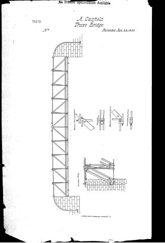
Augustus Canfield's Patent Drawing for an Improvement in the Construction of Iron Bridges

National Archives, Restored Patent Drawings (Record Group 241) · Full-size scan at the National Archives · Catalog record
Text on the drawing
Words on the drawing as machine-read by the National Archives; not checked. Useful mainly for searching.
14. BRIDGE / [21] Truss, / $2- / Ougustus Canfreldo in the Construction of Sron Bridges. / CLASS TION / PalentedSune 29 1833. / 7621- / DIVISION. / MM / am / MAR / The Tension Bridge 80 feet span. / Head brace Vertical projection / 000 / S.S. Spiral Springs to allow the iron to contract and expand / 2nd Upper String / A.B. Upper Strings / Upper String / 000 / of / The Strings at SSSS sustain no stress from a weight on the Bridge / and of course it would be equally strong without them. - / Horizontal projection / Foot of brace Vertical projection / He / C.D. / Braves / Brace / 6.E Posts / II Crofs Brace / Fool Preees / Lower String / DOOL / 2nd hower String / Horezontal projection
USPTO scan
The patent as scanned by the USPTO
-
 Page 1
-
 Page 2
-
 Page 3


U.S. Patent and Trademark Office · Google Patents
Published accounts: journal notice
Notice in the monthly list of patents, with remarks
Journal of the Franklin Institute, new ser., vol. 12 (1833), p. 400 · View the page
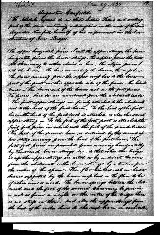
16. For an improvement in the Construction of Iron Bridges; Augustus Canfield, Paterson, Essex county, New Jersey, June 29.
Remarks. This is a chain bridge, and is, on the drawing, called a tension bridge. It is represented as having a span of eighty feet; and as having two string pieces, or chains, one above the other, in a straight line, or rather arching a little upwards. The upper and lower string pieces, as shown in the drawing, are ten in number, and the links are of course eight feet in length; they are to be of wrought iron; the distance between the upper and lower string pieces is also represented as eight feet. Vertical bars connect the upper and lower string pieces at each joint, thus dividing the whole into squares of eight feet; diagonal braces, pointing from the centre towards the abutments, are placed in each of the squares; these braces are to be of cast iron. There is no claim made, but "the inventor believes this to be the best arrangement of the materials that can be made." He also remarks that "in this construction, the stress upon each part by any given pressure, is a matter of simple calculation;" we are apprehensive, however, that a correct calculation would not confirm the opinion that this is "the best arrangement of the materials which could be made;" we, however, leave it to others to institute the inquiry, for which we will readily find room in our pages.
About this record
- Patentee
- DATAMP
- Date
- the Name and Date index of patents, DATAMP, USPTO records
- Invention
- DATAMP
- Listed in
- the Name and Date index of patents, DATAMP, USPTO records, Jim Shaw's X-patent list, the Journal of the Franklin Institute, Burke's List of Patents (1847)
- in_burke