

Drawings and documents
National Archives restored drawings: drawing
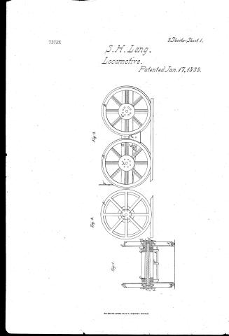
Stephen H. Long's Patent Drawing for a Compound Cam with Four Cam Rods


National Archives, Restored Patent Drawings (Record Group 241) · Full-size scan at the National Archives · Catalog record
Text on the drawing
Words on the drawing as machine-read by the National Archives; not checked. Useful mainly for searching.
Sheet 1. (Recur Jarry 5' 1844.) / $150 / LONG'S COMPOUND CAM WITH FOUR CAM RODS / Patented Jany 17. 1533. / 121 / STEAM. / ENGINES. / Walves / Fig. 3 / (153) / Valve Gear. / CLASSI FICATION / of / of / 7372.x / DIV ISION. / of / of / E. / ID / RB / E' / Fig.1. / Fig. / de / at / Eig. / Fig / is / at / The Compound Cam mth Four Cam Rods devised by S.H. Long in 1831 and patented in /833 / Explanation of the rawings / Fig A side view of the cut off Cam with its yoke Cam / References / rod Sweep for / A The Cut- off Cam / EorE. The Compound Crank with its shaftand winch / Figh A side view of the Circular Cam with its Cam / A' The Circular Cam / for changing the gearing between the Cams and / Steam and thus reversing at pleasure the / red sweep fe / B The Cut- off Cam yoke / movemen ts of the Engine / Jig 3. cA horisontal plan or view of the Cam rods fe. / B The Circular Cam yoke / e oré' The Winch attached to the shaft of the Com- / arranged in justa position for the sake of / CorC' Cam rods communica between the Cams / pound shaft / another exhibiting more clearly their relations one to / and the slide valves of the Engine / forf' The arms of the Compound Crank connected / a. Circular plates or partitions on the sides of and / Figh A honsontal section through the centre of the / between the Cut.off Cams / Compound Cut. off Cam / b.b. Hooks as usual for shifting the gearing between / Note. graning the and ungearing of the the Cam rods / at The or g' with the upper ends of the sweeps DorD' / is effected following manner vrs; winch / Figs A horisontal section through the centre of the / the Cams and values / beingin the position as represented at e Jigs Land 2 / Compound Circular Cam / Cord Axle of the working wheels of the Socomotive / indining to the right the rods Fig 3 mill / Figh A horisontal section through the centre of the Com- / DorD' Sweeps or guides for regu lating the movements / be in gear and or 28084 out of The winch / pound Crank and urnch or of the working / of the Cam rods and for gearing and ungear / being equally inclined to the left the rodict 2 / shaft and its arms by means of which alter- / ing the same / and will be in gear and / and N°3 out of / -nate pains of the Cam rods are geared or un / Note. The lower ends of the sweeps are furnished with gear :-The winch being vertical all the rods will be / -geared with the slide valves of the Locomotive / suitable orifices through which the sliding parts of the out of year / steam Engine / Cam rods d or d' reciprooate their movements, the / N.B. Corresponding parts in all of the figures will / sweeps themselves being furnished with guides / Stephen H. Long: / be indicated by the same letters of reference / to regulate their vertically whenever a / change of gearing is to be effected / County of Ohio Hamilton / for / On thirtwenty nirthday of December 1843 before the subscriber a justice of the peace for said Coun ty / personally appeared Stephen He Long now of said County and State and made solemn oath that to the best of his The knowledge and / Cam and Four Cam Rods "for which Letters Patent of the United States were granted to him dated the Seventeenth day of / belief he is the inventor of a certain improvement in the construction of Locomotive Steam Engines denominated Compound / January 1833 and that the above drawings are as he verily believes, true delineations of the invention described in the said / Patent, and designated therein as the Compound Cam and Cam Rods / Richt Mulford / Justice of the Trease
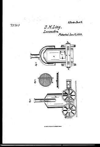
Sheet 2. 123. STEAM. / 3. LOCOMOTIVES. / [04] Locomotives. / KOILVOI IS / I H. Long / Patented 17,2aml, 1833, / 7372 / Locomotive Engine Sgo, / 16 / DIVISION. / 291 / F.8.1. section through wheels. References. Fif.2. inside of wheel. Fif.3.Side Elevation / of car and break. Fid.H. Side Elevation of Locomotive Fif. 3. front of Locometive / Fif 6 fire grate. Fif.7. virtical section of boiler, Fif 8, top of boiler Fig.9. top view of / Engines. Fif 10 side versof Engines, - A. rim of wheel showing flangerB. hub. d bones / rung on anle. E hinch pin. F. break F'handle of do, G. car frame Heylinder t.coupting Kiboiler. K.cone. / I. S. smoke pipe. M. grate, Nashpit. 0 steam chamber. P. fire door, Qman hole, R,outside jacket / Excentries for working the valves, Ivalve rods Fiel. / Fuf.1. / Fiffs. / (D1 / I'm / LA / Patent Office Mar: 11. 1842. / Made under the direction of the Commifriener of / Patents in conformity with act of Congrep. March 1837, / not / Commissioner of Jatents,
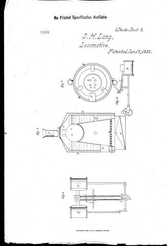
Sheet 3. Locomotives / LOCOMOTIVES. / 123. STE A M. / CLASSIFICATION / STEAM / X-WAIC / I. / Fif.7. / Fif.9. / Fifs / eip / Fif.10. / T'
Sheet 4. of / it / 111 / 1) / FR / is / to / y'o / GRA / '9.S.A / NOISLAIS / T-CLEL / 128. STEAM. / LOCOMOTIVES. / Locomotives. / NOLLVOLUISSVIO / 3. / [v]
USPTO scan
The patent as scanned by the USPTO
-
 Page 1
-
 Page 2
-
 Page 3
-
 Page 4
-
 Page 5
-
 Page 6
-
 Page 7
-
 Page 8
-
 Page 9
-
 Page 10
-
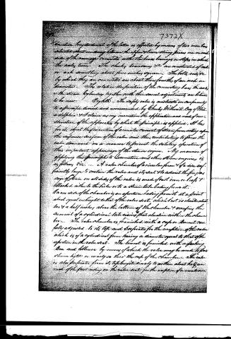 Page 11
-
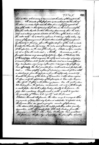 Page 12
-
 Page 13


U.S. Patent and Trademark Office · Google Patents
Published accounts: journal notice
Notice in the monthly list of patents, with remarks
Journal of the Franklin Institute, new ser., vol. 12 (1833), p. 22 · View the page
13. For a Locomotive Steam Engine for Rail-roads, denominated the PENNSYLVANIA LOCOMOTIVE; S. H. Long, Lieutenant Colonel of Engineers of the United States, January 17.
Remarks. Without drawings we cannot give a competent idea of the various points of arrangement which are considered as new in the different parts of this locomotive engine and carriage. The specification occupies sixteen pages, independently of the references to the drawings, which require three more. The improvements contemplated are intended to combine economy and efficiency, and are said to consist in the invention of machinery altogether new; of new modifications of machinery before known; and of combinations of machinery, both new and old, in a way not heretofore applied to locomotive steam carriages. Those parts, or combinations, which are considered as new being so designated in the course of the description, without being summed up at its end. The wheel, besides the ordinary flanch on its periphery, is to have a second on the opposite edge of the tread, projecting inwards towards the hub; this flanch is incorporated with the spokes, and is intended to strengthen the wheel. The hub is to be cast tubular, its thickness must be as equable as possible, and the boxes which are to receive the axle are to be let into it, and secured by bolts passing through flanches prepared for the purpose. These points constitute a part of the novelties claimed. The axles and their adjustments are to differ from those now in use. They are to be of a uniform size throughout, without journals, necks, or shoulders, and they are to be firmly connected to the wheels. Rings, or bands, are to be attached to the axles by pins, or screws, and are to turn in grooves which may serve as receptacles for oil; this arrangement is considered as new. Wedge formed breaks, or convoys, are to be applied between the foremost and hindmost wheels, passing either upwards or downwards, the sides of them to be curved to adapt them to the wheels. There is nothing new in this part, such breaks being used upon the Baltimore and Ohio, and other rail-roads. The boiler is to be cylindrical, and is to stand on its end; at its upper extremity it is to be terminated by the frustrum of a direct cone. The boiler is described in the Franklin Journal, for 1827, with other improvements, the invention of Colonel Long; as it now appears, however, it is somewhat modified, though not materially altered. A casing of sheet iron surrounds the boiler, and serves as a flue to conduct off the smoke and heated air; from opposite sides of this casing two flues pass off and unite in one vertical chimney; this chimney is made to work on tubular swivel joints so that it may be lowered to pass under bridges or through tunnels; these joints are viewed as new. The bars of the grate are formed of sheet iron, the section of them being somewhat like an inverted U, closed nearly together at the edges; the hollow space is to be filled with fine clay; this and some other points in its arrangement are also claimed as new. The steam cylinders are to be two in number, placed horizontally; they are to receive their supply from the same steam chest, each having a slide valve for that purpose. These two cylinders, with a steam chest, in common, is said to be new. The cams and cam rods for operating upon the valves, are also considered as new in principle. The manner of constructing the carriage is next described, and "the relative disposition of the connecting bars, the axles, and the steam cylinders, together with their several adjustments, are believed to be new." The safety valves are constructed on a principle devised by Chas. Wetherill, Esq. of Philadelphia, modified, however, in a novel manner, by the patentee. It is designed to prevent a counter current of steam from acting upon the upper surface of the valve, and pressing it down so as to impede its action. The principle of causing a current of steam to be forced on ignited anthracite to promote its combustion, as devised by Mr. Wetherill, is also applied in a way which is particularly described; the consent of Mr. Wetherill to the adoption of the improvements having been obtained. This last part, we presume, is not considered as forming any part of the patent, as no exclusive right has been acquired there-. for by Mr. Wetherill, and he must be considered as having abandoned to the public any right which he may have possessed. The drawings which accompany the specification give a clear exhibition of the arrangement of the whole machinery, which is ingenious and compact; we are apprehensive, however, that there is not a sufficient surface exposed to the action of heat to keep up the requisite supply of steam; and that the common objection arising from the packing down of the anthracite, by the continued vibration on a rail-road, will interfere with the efficient action of that fuel.
About this record
- Patentee
- DATAMP
- Date
- the Name and Date index of patents, DATAMP, USPTO records
- Invention
- DATAMP
- Listed in
- the Name and Date index of patents, DATAMP, USPTO records, Jim Shaw's X-patent list, the Journal of the Franklin Institute, Burke's List of Patents (1847)
- The Name and Date index lists this patent twice.
- in_burke
Shaw: also: Long, S. H. 1833-01-17