

Drawings and documents
National Archives restored drawings: drawing
Oscar Willis' Patent Drawing for a Swinging Riddle for Washing Gold

National Archives, Restored Patent Drawings (Record Group 241) · Full-size scan at the National Archives · Catalog record
Text on the drawing
Words on the drawing as machine-read by the National Archives; not checked. Useful mainly for searching.
90. ORE. / [3] / Washers. / $350 / Oscar Willis / CLASSE / 72224 LIV ISION. / Twinging Biddle for washing Gold / Vol th pg. 401. / Patented Sept. 5th 1832. / Jig2 / References. / a.a.a a frame. 6'frame to support the ziddle (c. C asles. / 2.2.2. crofs pieces see stig 2 jee hinges by which the ziddle fisattached. / g.g.g.g chains. D. hopper of. of side pieces. E the ripple / I Platform. H represents washed Iravel. / made under the Incotion the Commissioner of Patents / Patent office sighly 1841. / in conformity with act of 3? march 1837. / Commissioner of Patents
USPTO scan
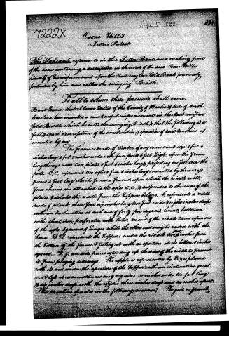
The patent as scanned by the USPTO
-
 Page 1
-
 Page 2
-
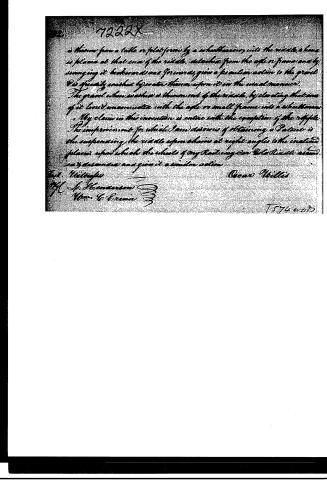 Page 3


U.S. Patent and Trademark Office · Google Patents
Published accounts: journal notice
Notice in the monthly list of patents, with remarks
Journal of the Franklin Institute, new ser., vol. 11 (1833), p. 171 · View the page
7. For an Improvement upon the Rail-way Car Gold Riddle; Oscar Willis, Burke county, North Carolina, September 5.
Remarks. The rail-way car gold riddle, is described in a former number. The improvement now patented consists in suspending a riddle by four chains, attached above to proper frame work. The bottom of the riddle is to be of sheet iron, and perforated with numerous holes.
Published accounts: journal notice
Notice in the monthly list of patents, with remarks
Journal of the Franklin Institute, new ser., vol. 13 (1834), p. 181 · View the page
Grooved rollers, such as are now in use, are to be employed to make ridges crosswise of a bar, or plate, from which nails are to be cut, which ridges, in the process of cutting, are to form the heads of the nails. These are now to be cut with the ordinary machinery, lengthwise of the bar, or plate, so that the grain of the iron will be in the proper direction for the requisite toughness. "What I claim as my invention, is, the grooving of the ridges on the bars, or plates, for the heads of nails, by the application of the roller, FYLER'S Improved Escapernent. and the process of cutting the nails lengthwise of the bar, or with the grain of the material." A patent for a procedure identical with the foregoing, was granted on the 25th of October, 1832, to Freeman Palmer, of Buffaloe, New York, and is noticed at page 233, vol. x. [TO BE CONTINUED.] SPECIFICATIons of American PATENTS. Specification of a patent for an improvement in the Escapement of Clocks or Time Pieces. Granted to ORSIMUS R. FYLER, Bradford, Orange county, Vermont, September 6, 1832.
Remarks. To all whom it may concern, be it known, that I, Orsimus R. Fyler, of Bradford, in the county of Orange and state of Vermont, have invented an improvement in the mode of constructing the escapements of clocks, or time pieces, and that the following is a full and exact description thereof. Instead of using springs upon the pallets of verges, in the manner described by me in the specification of a patent for improvements in wooden and other clocks, granted to me on the 13th day of June, 1831, I apply a spring to act upon the pin, or arbor, on which the verge vibrates, in a way to be presently described; varying the same so as to adapt it to the particular construction of the pallets; or sometimes I give to the pin itself sufficient length to allow of its operating by its own elasticity, in such a manner as to effect the object which I have in view; my improvement consisting in the practical adoption of a principle, which may be variously modified. My usual method of attaching a spring to, or causing it to act upon, the pin, is as follows. I take two disks, usually of brass, which may be about an inch in diameter, and a line, more or less, in thickness; through each of these plates, or disks, I make a small hole, near to the periphery thereof, as shown at A, in the accompanying drawing. To one of the disks or plates, I attach a spring, which may consist of wire, coiled, or bent, in a serpentine direction, or made in any other manner. In the drawing, the spring B, is represented as serpentine, attached to the plate by one end; a loop, or eye, in the other embracing the pin upon which the verge socket turns. For a pendulum vibrating half seconds, and with a bob weighing about eight ounces, I have found wire No. 30, to be of a suitable size. To receive this spring, I make a hole through the front clock plate, nearly as large as the before named disks, one of which is to be attached on each side of the plate, so as to stand parallel to each other, with the holes for the pin coinciding, and a space between them forming a chamber for the spring. I then pass an elastic metallic pin, through the holes in the disks, which must be sufficiently large to allow it to have some play within them. One end of the pin has a swivel head, the other end being fitted to receive the verge socket. Sometimes I enlarge the hole in the outside disk, and support the FYLER'S Improved Escapement. outward end of the pin by means of a bridge placed outside of the socket of the verge; care being taken to make the aperture in which the pin rests, something larger than the pin itself. The verge and socket I construct in the way usual in recoil escapements, taking care that all the parts be made as light as can be eligibly done. The verge I usually allow to embrace about one-fifth of the circumference of the balance wheel, escaping in the common manner, taking care to place the pin which supports the verge, as near to the crown or balance wheel, as can be conveniently done, so that the recoil may be increased upon the horizontal pallets, and proportionably diminished upon the vertical section of the verge; the horizontal pallets being most relieved by the action of the spring, as is known to those scientifically acquainted with the subject. In fig. 2 of the drawing, the verge is represented as placed upon the pin, under the crown or balance wheel.
About this record
- Patentee
- DATAMP
- Date
- the Name and Date index of patents, DATAMP, USPTO records
- Invention
- DATAMP
- Listed in
- the Name and Date index of patents, DATAMP, USPTO records, Jim Shaw's X-patent list, the Journal of the Franklin Institute, Burke's List of Patents (1847)
- in_burke