

Drawings and documents
National Archives restored drawings: drawing
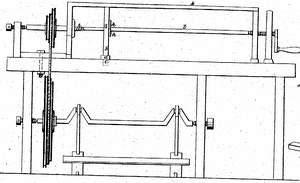
Giles Dayton and Andrew Mallory's Patent Drawing for a Whip Engine for Turning Whip Stocks


National Archives, Restored Patent Drawings (Record Group 241) · Full-size scan at the National Archives · Catalog record
Text on the drawing
Words on the drawing as machine-read by the National Archives; not checked. Useful mainly for searching.
Sheet 1. $2- 7017X / 142. WOOD WORKING / CLASSIFICATION / 1. LATHES. / [175] Gage Lathes. / 3872 / Giles Dayton & Andrew Mallory Apr27. 1832 / DIV ISION. / Whip Engine for Turning Whip Tocks. / Vol.15 pg. is / Cutting iron / Patentio tpil 27th / View of the cutting edge / KII / References.a the J pieces B the Jack. c slide. d cat / the hinge. off their tenons. go the cutting iron: hh. mitred / l the mandrel K.K the guiding frame. l the puce of wood / to be turned. / 1001 / Patent offies / Made under the direction of the Comm / in Conformity with Got of 3'd march / Hislman freit / MLSumo / Commissioner
Sheet 2. Dayton & Mallory, / 7017X / Gage Lathe. / IV: 272 / Patented Apr.27,1832. / it / Dinelt.
USPTO scan
The patent as scanned by the USPTO
-
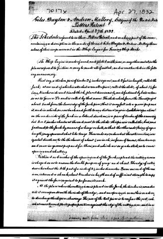
 Page 1
-
 Page 2
-
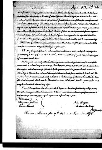 Page 3


U.S. Patent and Trademark Office · Google Patents
Published accounts: journal notice
Notice in the monthly list of patents, with remarks
Journal of the Franklin Institute, new ser., vol. 10 (1832), p. 242 · View the page
35. For an Engine for Turning Whip Sticks, or Handles; Andrew Mallory, Russel, Hampden county, Massachusetts, April 27.
Remarks. This engine is intended to be used in turning whip handles tapering, either regularly or otherwise, and it may also be employed for helves, or other sticks, whether cylindrical or tapering. The stick to be turned may be fixed in the mandril of a common turning lathe, and the apparatus here patented placed in front of it. It consists, in part, of a frame with parallel sides, equal in length to the length of the stick to be turned. A piece carrying a cutter, which operates as a gouge and chisel, slides along in grooves on these sides. This sliding part consists of two bars hinged together at one end, and capable of being opened or closed at the other; and near to this latter end is fixed the cutter before spoken of. The stick to be turned rests on a hollow bearing of metal on the lower piece, and the cutter passes through the upper piece. It is evident that if these two parts, which form the hinged sliding bar, recede from each other as the bar advances, the article operated upon by the cutter will have a corresponding increase in its diameter. To effect this, each of the bars has a tongue on it which slides in a groove on one of the cheeks of the frame. There are, of course, two grooves, and if these were parallel to each other, the two parts of the sliding bar would keep at the same distance apart, and the article turned would be cylindrical; but if the grooves recede, the bars will be gradually separated, and the article will be tapered.
DATAMP: illustration
Illustrations from DATAMP

DATAMP (Directory of American Tool and Machinery Patents), via the Internet Archive · Archived DATAMP page
About this record
- Patentee
- DATAMP
- Date
- the Name and Date index of patents, DATAMP, USPTO records
- Invention
- DATAMP
- Listed in
- the Name and Date index of patents, DATAMP, USPTO records, Jim Shaw's X-patent list, the Journal of the Franklin Institute, Burke's List of Patents (1847)
- The residence comes from the Franklin Institute's journal.
- in_burke