

Drawings and documents
USPTO scan
The patent as scanned by the USPTO
-
 Page 1
-
 Page 2
-
 Page 3
-
 Page 4
-
 Page 5


U.S. Patent and Trademark Office · Google Patents
Published accounts: specification
Specification printed in the Journal of the Franklin Institute
Journal of the Franklin Institute, new ser., vol. 9 (1832), p. 135 · View the page
Text of the specification as printed in the Journal, from OCR; not proofread.
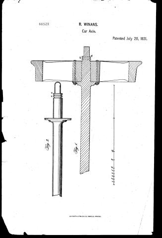
Specification of a patent for an improvement in the construction of the axles or bearings of rail-way, or other wheeled carriages. Granted to Ross WINANS, city of Baltimore, July 20, 1831. To all whom it may concern, be it known, that I, Ross Winans, have invented an improvement in the construction of the axles, or bearings, of rail-way, or other wheeled carriages, and that the following is a full and exact description thereof. The axle, with my improved journals, or bearings, may be made straight, and the wheels placed thereon in the usual way; but instead of forming the bearings under the body of the carriage, and within the naves, or hubs, of the wheels, there to sustain the weight of the load, I extend the axles out at each end, projecting beyond the naves to such a length as shall enable me to form them into gudgeons. The lengths and diameters of these gudgeons, I regulate according to the load they are intended to sustain, and to other circumstances. In all cases, however, the value of my invention depends upon the gudgeons having their diameters as small as a due attention to the strength required will allow. The causing the axles to run in boxes, or upon bearings without the naves, admits of their being made much smaller than usual, the degree of diminution which I have found to answer well in practice, will hereafter be stated. They should be formed of good wrought iron, and case-hardened; or overlaid, or cased, with the best steel and hardened, which materially diminishes the extent of bearing surface necessary to enable them to receive and resist the pressure of the load, and their tendency to wear; they may WINAN'S Improved Axles. 1 therefore be short, and are consequently strong, when of, comparatively, very small diameter. The tendency to lateral movement is checked, or limited by forming the end, or point of the axle, or gudgeon, so as to be met occasionally by the external cap, or cover, of the gudgeon box, when lateral pressure occurs. By placing the bearing outside, (as aforesaid,) the diameter of the wheels may be enlarged with more advantage than formerly, as the axles between the wheels may be made of any required strength, (to resist the increased stress thrown on to that part of them by an enlargement of the wheels,) without affecting the size, or strength, of the bearing journals. By the foregoing means, the leverage of the wheels, (or the mechanical advantage with which the moving power acts, to overcome the resistance to motion,) is increased, and consequently the friction or resistance to motion in rail-road carriages, diminished to a greater extent than heretofore. This improvement in the axles and journals of rail-way carriages, was devised and carried into operation on my experimental rail-way, and exhibited to various persons in the early part of the year 1827; and it was put into practical operation, under my direction, on the Baltimore and Ohio, and on the Liverpool and Manchester, rail-roads, in the early part of 1829, in connexion with another improvement for the further diminution of friction, by means of a revolving bearing, or friction wheel, for which other improvement a patent was granted to me on the 11th of October, 1828. I constructed for use, on the latter of the before mentioned roads, a number of cars with the axles and journals, or gudgeons, of various descriptions and dimensions; the gudgeons, or immediate place of bearing for the load, varied from 14 to 24 inches in diameter, and from 1 to three inches in length. Some of them were made of wrought iron, and case-hardened, and some of iron overlaid with steel and hardened. The axles between the wheels were mostly of wrought iron of from 2½ to three inches in diameter. Several cars, however, were constructed with hollow cylindrical cast iron axles, secured to the wheels by flanches on the ends of the axle, and bolts, the gudgeons being separate pieces firmly fixed into the naves of the wheels. (Wood may also be used for the axle to keep the wheels in their parallel relation to each other, with steeled gudgeons, as aforesaid, to receive the bearings.) The result of experience by the practical use of those cars for the conveyance of loads from three to six tons, and under various circumstances, is that, (for the support of a given load,) the gudgeons or bearing for the load might, in the manner herein specified, be safely used of from one-third to one-half less in diameter than those in common use, without impairing, but rather increasing, the strength and durability of a car; and the diameter of the wheels finding a less early practical limit, it is evident that a saving in the moving power is effected, as the power acts at a mechanical advantage equivalent to the increased ratio of the diameter of the wheel to that of WINAN'S Improved Axles. the axle. These gudgeons, so constructed, were exhibited by me in England, as before stated, and have been adopted there without my deriving any advantage therefrom; as, by the laws of that country, I could not secure the invention by patent, after having publicly exhibited it. The object of the invention, and a practical demonstration of its utility having been shown, its application and adaptation to the different rail-road carriages, burthen wagons, locomotive engines, &c. and to the different bearing boxes that may be preferred for different purposes, (either revolving, or common,) will be evident, and easy, to any person acquainted with the building of rail-way carriages. But to render it still more so, the following general directions and proportions are given, which I think will be found to be a near approximation to what will be required in practice. When it is intended to convey loads of from two and a half to three and a half tons, and to use wheels of from two and a half to three feet in diameter, the general diameter of the axles may be from two and three-fourths to three inches, and extending through and beyond the naves of the wheels on each side, far enough to go under and conveniently receive the side frame of the load bed, and to have their ends turned, or formed into gudgeons about two and a half to three inches in length, and from one and a half to two inches in diameter. On the four gudgeons thus formed, the carriage body rests by means of any hard metal bearings attached to the before mentioned side pieces; which side pieces are so framed with the cross pieces of the bed as to go on the outside of the wheels, either over or under the gudgeons, as convenience may require. The friction occasioned by the tendency to a lateral movement of the gudgeon is limited by causing the end cover of the bearing to meet the end of the gudgeon as near to the centre of action as possible. When my revolving box is intended to be used, this end is attained by forming the end perfectly square; and when the common box is used, by forming the end of the gudgeons convex or rounding. In consequence of the small extent of bearing surface embraced by the bearing on the journal, the bearing box, (to guard against wear,) should be made as hard as the use of the most favourable materials for that purpose would permit. The oiling or lubrification of the gudgeons may be effected in any of the usual or convenient ways. But to guard as much as possible against the oil working from the gudgeons on to the rail wheels, it is adviseable to turn one or two small rings, or grooves, on a portion of the axle between the gudgeon and the nave of the wheel, which will obviate that difficulty. I do not intend to be understood as claiming all merely projecting axles with bearing beyond, or external to, the wheels; the single wheel of Sargeant's and of Palmer's rail-way carriage, for single rail-ways, had projecting axles, and several kinds of rail-way carriages have been devised with four wheels, each having separate axles, with both inside and outside bearings, with a view to turning curves with facility. A carriage was made at Liverpool, in England, at a later date than my invention, with outside bearings of the usual size for the purVOL. IX. No. 2.-FEBRUARY, 1832. 18 1 JENNINGS' Improvement in Lamps. pose of using a broad-body, temporarily, and without any view to the object of this improvement, nor effecting the like purpose. My invention is sufficiently distinguished from all others before known and used by the new and useful effect produced in the manner aforesaid. I therefore declare that the improvement, or improvements, above explained and described, in diminishing the resistance to motion in wheeled carriages to be used on rail-ways, which I claim as my own invention, is the extending the axles each way outside of a pair, or pairs, of wheels, far enough to form external gudgeons to receive the bearing box of the load body, and diminished as aforesaid, with a view to lessen the resistance of friction, as small as its situation, with the use of the most favourable metal for wear, will permit. Thus conveniently increasing the leverage of the wheels, without impairing their effective strength or durability. ROSS WINANS. Fig. 1. Fig. 2. Fig. 1. Axle with flat end. Fig. 2. Axle with round end. The dotted lines show the rings or grooves.
Published accounts: journal notice
Notice in the monthly list of patents, with remarks
Journal of the Franklin Institute, new ser., vol. 9 (1832), p. 54 · View the page
The claims are to the right and left handed screws, and to the particular construction of the wheels. 43. For an improvement in the Axles of Wheels for Railway Carriages; Ross Winans, city of Baltimore, July 20.
Remarks. (See the specification.)
Published accounts: journal notice
Notice in the monthly list of patents, with remarks
Journal of the Franklin Institute, new ser., vol. 9 (1832), p. 135 · View the page
This is the common screw press, in which a wheel and pinion are used to act upon the screw. There is to be a horizontal shaft upon which a pinion is to be placed; this pinion takes into a horizontal crown wheel at the head of the screw. In the follower there is a nut in which the screw works, and causes it to descend. The shaft carrying the pinion may be turned by a crank, and upon this shaft a whirl, or pulley, is fixed, for the purpose of suspending a weight by a cord from its periphery, where continued pressure is wanted, as in pressing cheese. There is no claim made, the patentee probably supposing that the application is altogether new. Many presses, however, have been made in which the power of the wheel and pinion has been employed in the working of the screw. SPECIFICATIONS OF AMERICAN PATENTS. Specification of a patent for an improvement in the construction of the axles or bearings of rail-way, or other wheeled carriages. Granted to Ross WINANS, city of Baltimore, July 20, 1831.
Remarks. To all whom it may concern, be it known, that I, Ross Winans, have invented an improvement in the construction of the axles, or bearings, of rail-way, or other wheeled carriages, and that the following is a full and exact description thereof. The axle, with my improved journals, or bearings, may be made straight, and the wheels placed thereon in the usual way; but instead of forming the bearings under the body of the carriage, and within the naves, or hubs, of the wheels, there to sustain the weight of the load, I extend the axles out at each end, projecting beyond the naves to such a length as shall enable me to form them into gudgeons. The lengths and diameters of these gudgeons, I regulate according to the load they are intended to sustain, and to other circumstances. In all cases, however, the value of my invention depends upon the gudgeons having their diameters as small as a due attention to the strength required will allow. The causing the axles to run in boxes, or upon bearings without the naves, admits of their being made much smaller than usual, the degree of diminution which I have found to answer well in practice, will hereafter be stated. They should be formed of good wrought iron, and case-hardened; or overlaid, or cased, with the best steel and hardened, which materially diminishes the extent of bearing surface necessary to enable them to receive and resist the pressure of the load, and their tendency to wear; they may WINAN'S Improved Axles. 1 therefore be short, and are consequently strong, when of, comparatively, very small diameter. The tendency to lateral movement is checked, or limited by forming the end, or point of the axle, or gudgeon, so as to be met occasionally by the external cap, or cover, of the gudgeon box, when lateral pressure occurs. By placing the bearing outside, (as aforesaid,) the diameter of the wheels may be enlarged with more advantage than formerly, as the axles between the wheels may be made of any required strength, (to resist the increased stress thrown on to that part of them by an enlargement of the wheels,) without affecting the size, or strength, of the bearing journals. By the foregoing means, the leverage of the wheels, (or the mechanical advantage with which the moving power acts, to overcome the resistance to motion,) is increased, and consequently the friction or resistance to motion in rail-road carriages, diminished to a greater extent than heretofore. This improvement in the axles and journals of rail-way carriages, was devised and carried into operation on my experimental rail-way, and exhibited to various persons in the early part of the year 1827; and it was put into practical operation, under my direction, on the Baltimore and Ohio, and on the Liverpool and Manchester, rail-roads, in the early part of 1829, in connexion with another improvement for the further diminution of friction, by means of a revolving bearing, or friction wheel, for which other improvement a patent was granted to me on the 11th of October, 1828. I constructed for use, on the latter of the before mentioned roads, a number of cars with the axles and journals, or gudgeons, of various descriptions and dimensions; the gudgeons, or immediate place of bearing for the load, varied from 14 to 24 inches in diameter, and from 1 to three inches in length. Some of them were made of wrought iron, and case-hardened, and some of iron overlaid with steel and hardened. The axles between the wheels were mostly of wrought iron of from 2½ to three inches in diameter. Several cars, however, were constructed with hollow cylindrical cast iron axles, secured to the wheels by flanches on the ends of the axle, and bolts, the gudgeons being separate pieces firmly fixed into the naves of the wheels. (Wood may also be used for the axle to keep the wheels in their parallel relation to each other, with steeled gudgeons, as aforesaid, to receive the bearings.) The result of experience by the practical use of those cars for the conveyance of loads from three to six tons, and under various circumstances, is that, (for the support of a given load,) the gudgeons or bearing for the load might, in the manner herein specified, be safely used of from one-third to one-half less in diameter than those in common use, without impairing, but rather increasing, the strength and durability of a car; and the diameter of the wheels finding a less early practical limit, it is evident that a saving in the moving power is effected, as the power acts at a mechanical advantage equivalent to the increased ratio of the diameter of the wheel to that of WINAN'S Improved Axles. the axle. These gudgeons, so constructed, were exhibited by me in England, as before stated, and have been adopted there without my deriving any advantage therefrom; as, by the laws of that country, I could not secure the invention by patent, after having publicly exhibited it. The object of the invention, and a practical demonstration of its utility having been shown, its application and adaptation to the different rail-road carriages, burthen wagons, locomotive engines, &c. and to the different bearing boxes that may be preferred for different purposes, (either revolving, or common,) will be evident, and easy, to any person acquainted with the building of rail-way carriages. But to render it still more so, the following general directions and proportions are given, which I think will be found to be a near approximation to what will be required in practice. When it is intended to convey loads of from two and a half to three and a half tons, and to use wheels of from two and a half to three feet in diameter, the general diameter of the axles may be from two and three-fourths to three inches, and extending through and beyond the naves of the wheels on each side, far enough to go under and conveniently receive the side frame of the load bed, and to have their ends turned, or formed into gudgeons about two and a half to three inches in length, and from one and a half to two inches in diameter. On the four gudgeons thus formed, the carriage body rests by means of any hard metal bearings attached to the before mentioned side pieces; which side pieces are so framed with the cross pieces of the bed as to go on the outside of the wheels, either over or under the gudgeons, as convenience may require. The friction occasioned by the tendency to a lateral movement of the gudgeon is limited by causing the end cover of the bearing to meet the end of the gudgeon as near to the centre of action as possible. When my revolving box is intended to be used, this end is attained by forming the end perfectly square; and when the common box is used, by forming the end of the gudgeons convex or rounding. In consequence of the small extent of bearing surface embraced by the bearing on the journal, the bearing box, (to guard against wear,) should be made as hard as the use of the most favourable materials for that purpose would permit. The oiling or lubrification of the gudgeons may be effected in any of the usual or convenient ways. But to guard as much as possible against the oil working from the gudgeons on to the rail wheels, it is adviseable to turn one or two small rings, or grooves, on a portion of the axle between the gudgeon and the nave of the wheel, which will obviate that difficulty. I do not intend to be understood as claiming all merely projecting axles with bearing beyond, or external to, the wheels; the single wheel of Sargeant's and of Palmer's rail-way carriage, for single rail-ways, had projecting axles, and several kinds of rail-way carriages have been devised with four wheels, each having separate axles, with both inside and outside bearings, with a view to turning curves with facility. A carriage was made at Liverpool, in England, at a later date than my invention, with outside bearings of the usual size for the purVOL. IX. No. 2.-FEBRUARY, 1832. 18 1 JENNINGS' Improvement in Lamps. pose of using a broad-body, temporarily, and without any view to the object of this improvement, nor effecting the like purpose. My invention is sufficiently distinguished from all others before known and used by the new and useful effect produced in the manner aforesaid. I therefore declare that the improvement, or improvements, above explained and described, in diminishing the resistance to motion in wheeled carriages to be used on rail-ways, which I claim as my own invention, is the extending the axles each way outside of a pair, or pairs, of wheels, far enough to form external gudgeons to receive the bearing box of the load body, and diminished as aforesaid, with a view to lessen the resistance of friction, as small as its situation, with the use of the most favourable metal for wear, will permit. Thus conveniently increasing the leverage of the wheels, without impairing their effective strength or durability. ROSS WINANS. Fig. 1. Fig. 2. Fig. 1. Axle with flat end. Fig. 2. Axle with round end. The dotted lines show the rings or grooves. Specification of a patent for an improvement in Lamps for the combustion of evaporable fluids. Granted to ISAIAH JENNINGS, of the city of New York, August 1, 1331. To all whom it may concern, be it known, that I, Isaiah Jennings, of the city of New York, have invented an improvement in the common lamp, which adapts it especially to the combustion of the combination of alcohol and spirits of turpentine, and of other essential oils and ingredients, for the use of which ingredients letters patent of the United States have been already issued to me, and which improvement in the lamp is also applicable to the combustion of other evaporable ingredients not specified in the letters patent above alluded to. And I do hereby declare that the following is a full and exact description of my said improvement in the lamp. Instead of a tube, constructed constructed in the ordinary manner, for conThe first English Steam-boat. taining the cotton, or other wick, which is in them allowed to project through the tube, or burner, and lighted at the top thereof, I make a brass, or other tube, which I cause to rise to a much greater height above the reservoir, or body, of the lamp than is usually done, say, for example, to the height of two inches. The upper end of this tube I close entirely, or simply drill a small hole through, of such size as may suit the ingredients to be burnt, but not generally exceeding one-thirtieth of an inch in diameter. Through the sides of the tube, and at about half an inch, more or less, from its lower end, where it joins the body of the lamp, I drill four, or any other number of similar holes. A tube thus constructed forms the principal feature of my improvement; and in order to use this lamp, I insert a wick of cotton, a bundle of fine wire, or of any other fibrous material which will raise the fluid from the lamp by capillary attraction; allowing the wick to raise to the upper end of the tube, and to descend into the fluid the vapour of which is to be burnt. When this lamp is to be lighted, all that is necessary is to apply flame to the small openings above described, when the vapour which escapes therefrom will be inflamed, and the heat generated by this inflammation operating upon the tube, will'increase the evaporation so as to produce a brilliant light, without the destruction of the wick, or other fibrous substance. What I claim as new, and as my improvement in this lamp, and which is applicable to such lamps as are now in use, is the tube, or burner, for containing the wick, or other fibrous substance, constructed in the manner, or upon the principles, hereinbefore explained. ISAIAH JENNINGS. The first English Steam-boat. THE following description of the first steam-boat, with the accompanying drawing, is extracted from an interesting little pamphlet just published by Mr. Effingham Wilson, entitled "An Account of the Origin of Steam-boats, in Spain, Great Britain, and America; and of their introduction and employment upon the River Thames, between London and Gravesend, to the present time." In enumerating the early practical philosophers of that sublime agent, steam, we regret that the author of the pamphlet has omitted to include the name of the French engineer, PAPIN. If the writer be not already apprised of this inaccuracy, he will find an account of the man and of his work, in the "Recueil Industriel," No. 54, for last June, * in one of the series of papers upon steam engines, written by Monsieur Arago, who, with some show of justice, claims, on behalf of Pepin, the honour of being the first to apply the agency of steam for the purposes of navigation. Jonathan Hulls' work was printed in the year 1737, Papin's in 1695-42 years anterior to Hull's. In a subsequent edition of his * See vol. iv. of this journal, p. 363. The first English Steam-boat. entertaining and tasteful little book, our author will doubtless refer to the paper we have quoted, and, (if he feel that Monsieur Arago has made out his case,) render justice to the foreigner, on the score of priority of invention. At all events, this is the earliest known drawing of a steam-boat. "The object now to be noticed, is the first steam-boat projected in Great Britain, by Jonathan Hulls, who obtained a patent for his invention, dated the 21st day of December, 1736. "In the following year he published a tract,* containing a description of his machinery, the title of which is presented to the reader at length, as it contains the interesting fact in the history of steam navigation, that the first attempt was directed to the single purpose of towing ships. 'A description and draught of a new invented Machine, for carrying Vessels or Ships out of, or into, any Harbour, Port, or River, against Wind and Tide, or in a Calm, for which his Majesty has granted Letters Patent, for the sole benefit of the Author, for the space of fourteen years. By Jonathan Hulls. London: Printed for the Author. 1737.' "From this authentic source the most ample details may be obtained; and in justice to the ingenious inventor, such as it is adviseable to extract shall be given in his own words. "The author introduces the description of his engine and the boat machinery, with the following general observations: Whereas several persons concerned in the navigation have desired some account of my invention for carrying ships out of, and into, harbours, ports, and rivers, when they have not a fair wind. But I could not fully describe this machine without writing a small treatise of the same, in which I shall endeavour to demonstrate the possibility and probability of the matter undertaken. There is one great hardship lies too commonly upon those who propose to advance some new, though useful scheme, for the public benefit.. The world abounding more in rash censure, than in a candid and unprejudicial estimation of things, if a person does not answer their expectations in every point, instead of friendly treatment for his good intentions, he too often meets with ridicule and contempt. But I hope this will not be my case, but that they will form a judgment of my present undertaking only from trial. If it should be said that I have filled this tract with things that are foreign to the matter proposed, I answer, there is nothing in it but what is necessary to be understood by those that desire to know the nature of that machine that I now offer to the world, and I hope that, through the blessing of God, it may prove serviceable to my country.' Then follows a long explanation, with definitions and demonstrations of the nature of the powers called into action, for which the reader is referred to the work itself; omitting the full recital here, because * This tract has been reprinted by Mr. Partington at the end of his Lectures on the Steam Engine, and it is introduced there with the following note. "This highly curious tract, which the editor has been permitted to copy, throws considerable light on the history of steam navigation. Its great rarity, however, has hitherto prevented its contents becoming generally known to the scientific world, a single copy having been sold for more than three guineas." The first English Steam-boat. it is more desirable to proceed at once to the description of the boat and machinery." Fig. 1. U a Ti R P Fig. 2. H LD TE Tr H B EID CL I Explanation of the wood engraving representing the first Steam-boat projected in England. Fig. 1. In some convenient part of the tow-boat there is placed a vessel about two-thirds full of water, with the top close shut. This vessel being kept boiling, rarifies the water into steam; this steam being conveyed through a large pipe into a cylindrical vessel, and there condensed, makes a vacuum, which causes the weight of the atmosphere to press on this vessel, and so presses down a piston that is fitted into this cylindrical vessel, in the same manner as in Mr. Newcomen's engine with which he raises water by fire. P. A pipe coming from the furnace to the cylinder. Q. A cylinder. R. A valve that stops the steam from coming into the cylinder, whilst the steam within the same is condensed. S. A pipe to convey the condensing water into the cylinder. T. A cock to let in the condensing water when the cylinder is full of steam, and the valve P is shut. U. A rope fixed to the piston that slides up and down the cylinder. This rope, U, is the same that goes round the wheel D in the machine. Improved Dividing Machine. A. The tow-boat. Fig. 2. B. Chimney coming from the furnace. C, C. Two pieces of timber framed together, to carry the machine. Da, D, Db. Three wheels on one axis, to receive the ropes F, Fa, Fb. Ha, Hb. Two wheels on the same axis with the fans I, I, I, I, I, I, which move alternately in such a manner, that when the wheels Da, D, and Db, move backward or forward, they keep the fans in a direct motion. Fb. A rope going from Hb to Db, that when the wheels Da, D, and Db move forward, moves the wheel Hb forward, which brings the fans forward with it. Fa. A rope going from the wheel Ha to the wheel Da, that when the wheels Da, D, and Db move forward, the wheel Ha draws the rope F, and raises the weight G, at the same time that the wheel Hb brings the fans forward. When the weight G is so raised, while the wheels Da, D, and Db, are moving backward, the rope Fa gives way, and the power of the weight G brings the wheel Ha forward, and the fans with it, so that the fans always keep going forward, notwithstanding the wheels Da, D, and Db, move backward and forward as the piston moves up and down the cylinder. L, L. Teeth for a catch to drop on from the axis, and are so contrived that they catch in an alternate manner, to cause the fans to move always forward, for the wheel Ha, by the power of the weight G, is performing its office, while the other wheel Hb goes back in order to fetch another stroke. The weight G must contain but half the weight of the pillar of air pressing upon the piston, because the weight G is raised at the same time as the wheel Hb performs its office, so that it is in effect two machines acting alternately by the weight of one pillar of air, of such a diameter as the diameter of the cylinder is! Improved Dividing Machine. [Rep. Pat. Inv. The Society of Arts have this month awarded their Gold Isis Medal to Mr. Andrew Ross, for some extremely ingenious and useful improvements in the dividing machine. The first improvement consists in a new mode of obtaining the divisions for circular dividing engines, depending, in the main, on the same principles as have already been employed, but varying in some of the details. Mr. Ross first divides his circle into forty-eight parts, by continued bi or tri sections, or by a combination of each method. The points thus formed being carefully marked on the limb of the circle, the intervals are then subdivided in the following manner:-An arc, equal to one of the spaces to be subdivided, is procured, Improved Dividing Machine. and is divided accurately, and to the same degree of minuteness as it is intended to divide the plate of the engine. The radius of this arc is to be equal to that of the engine, and whatever errors there may be in its original divisions, are to be corrected by the following process. A second arc, having an angular value equal to the first, with a radius only one-half or one-fourth as great, is, together with the first, attached and made concentric with the plate of the engine. The divisions of the first are transferred by means of radial lines to the second, the spaces between them being diminished, of course, in proportion to the radii of the respective arcs. When the second arc has received a counterpart of the divisions of the first, it is placed on the circumference of the engine plate, and there fixed, so that the divided arc shall occupy exactly its proper angular space on the limb of the plate. The divisions of the second arc are then transferred to the first or larger one, a single interval on this latter comprising two or four on the former, according as the radius of the one is twice or four times as great as that of the other. In this manner, the errors of any particular intervals become gradually distributed among the rest, and by repeating the process a sufficient number of times are reduced to invisible quantities. The second branch of Mr. Ross's improvements, consists of the apparatus by which the divisions of the engine plate, corrected as above described, are transferred to the arc of circles of other instruments. This is usually done by means of small teeth, cut on the edge of a large horizontal wheel: these teeth being acted upon by an endless screw, about an inch in diameter. The truth of such an engine depends, first, on a perfect equality between all the teeth in the wheel; and secondly, in an equality in all parts of the spiral formed by the threads of the screw, as well as in the inclination of those threads. The obstacles to perfect success in these particulars arising from slight differences in the density of the metal, or in the sharpness of the cutter, are such as have perhaps never been overcome entirely by the most celebrated artists, however nearly they may have approached it; and the wheel and screw, when once out of the maker's hands, are no longer susceptible of any correction, whatever errors may be discovered. Mr. Ross's engine consists likewise of two parts, which act as a toothed wheel and endless screw, but so constructed that each tooth of the wheel, and every part of the screw, admit of unlimited correction and adjustment by the person using it. The teeth of the wheel are only forty-eight, and consist of brass cogs into which are tapped steel screws, the axes of which lie in the plane of the wheel, and are at their ends tangents to the circumference. These ends being ground perfectly flat form the virtual faces of the teeth, and capable of being at any time advanced or withdrawn, give, therefore, to the wheel that perfect and constant power of adjustment which has been mentioned. The same power is obtained for the endless screw, by forming it of one deep thin thread, winding round a cylinder four or five inches in diameter. Into this thread are tapped ninety screws, at equal distances, having their axes parallel with the Meteorological Observations. [Mec. Mag. plane of the cylinder: the ends of these screws forming the stops to those in the cogs of the wheel, and like them, are capable of easy and unlimited correction. Thus the circumference of the wheel is divided into 4.320 equal spaces, every one of which may afterwards be corrected if required. Meteorological Observations for December, 1831. Therm. Barometer. Wind. Dew Water State of the weather, and Moon. Days. Sun 2 rise. P.M. rise. Sun 2 P.M. point Direction. Force. fallen in rain. Inches Inches. Inches. 22° 30° 29.70 29.80 16 W. Calm. 2 16 26 30.05 30.05 11 W. Moderate. 3 30 32 29.80 29.90 15 W. Blustering. 4 14 28 30.24 30.24 7 NW.SW. Moderate. 5 28 36 30.05 30.00 25 SSW.sw. do. 6 38 45 29.80 29.75 38 SW. W. do. .52 7 32 33 30.00 30.10 27 N. NE. do. 8 29 32 30.05 29.85 32 E. SE. do. 1.80 9 38 42 29.30 29.00 33 W. Blustering. D 10 28 42 29.70 29.70 33 W.SW. Moderate. 11 30 33 29.60 29.60 20 W. Blustering. 12 18 26 29.94 30.00 8 W. do. 13 23 48 30.00 30.00 30 SW. SW. Moderate. 14 35 49 30.15 30.20 31 W. do. 15 34 50 30.24 30.24 32 W. do. 16 33 50 30.24 30.20 35 W.NW. do. 17 30 48 30.15 30.10 37 NE. SE. Calm. 18 44 56 29.99 29.90 50 SW.SW. do. .3 19 51 56 29.80 29.83 39 SSW. W. Blustering. 20 38 46 30.05 30.05 29 W. Moderate. 21 32 36 29.85 29.90 30 W. do. .21 Cloudy-flying clouds. 22 20 30 30.20 30.20 13 N. do. 23 16 33 30.30 30.20 19 NE. E. do. 24 25 44 30.00 29.90 38 NE. do. 25 36 26 29.63 29.60 26 W. do. 26 4 8 30.10 30.20 6 W. do. 27-5 8 30.30 30 30 5 W. do. 28 2 25 30.30 30.20 12 SW.SW. do. 29 22 31 30.29 30.10 19 NE. S. do. 30 24 38 29.60 29.60 33 NE. NW. do. 31 20 32 29.90 29.94 19 W. do. .81 Rain-snow. .60 Rain. Mean 26.07 34.48 29.98 29.95 24.6 3.98 Remarks. Clear-cloudy. Clear day. Cloudy-clear. Clear day. Cloudy day. Fog-rain. Cloudy day. Cloudy-rain. Flying clouds-rain. White frost: cl'r. overcası Cloudy day. Clear day. Clear day. Clear day. Clear day. Clear day. Cloudy; hazy; rain in n't. Cloudy; clear; rain in n't. .1 Flying clouds-clear.
About this record
- Patentee
- DATAMP
- Date
- the Name and Date index of patents, DATAMP, USPTO records
- Invention
- DATAMP
- Listed in
- the Name and Date index of patents, DATAMP, USPTO records, Jim Shaw's X-patent list, the Journal of the Franklin Institute, Burke's List of Patents (1847)
- in_burke