

Drawings and documents
National Archives restored drawings: drawing
Philo C. Curtis' Patent Drawing for an Apparatus to be Connected with and to Form Part of a Steam Engine Boiler

National Archives, Restored Patent Drawings (Record Group 241) · Full-size scan at the National Archives · Catalog record
Text on the drawing
Words on the drawing as machine-read by the National Archives; not checked. Useful mainly for searching.
am Ещиех - Class 31- Feedwater Heaters / Condensers. / Surface, / (Heater) / 6535-+ / 'NOISIAIC / Shilo C Curlis / Care / PDD) Apparatus to be connected with & to form part of a Steam Engine Bailer. / Patented May 3ʳᵈ/1831 / vol 12. restored page 99 / herter / escape sleam entering / and / is / engine / force pump / Boilen / Lower / ending / supply / Emprem
USPTO scan
The patent as scanned by the USPTO
-
 Page 1
-
 Page 2
-
 Page 3
-
 Page 4
-
 Page 5


U.S. Patent and Trademark Office · Google Patents
Published accounts: specification
Specification printed in the Journal of the Franklin Institute
Journal of the Franklin Institute, new ser., vol. 8 (1831), p. 185 · View the page
Text of the specification as printed in the Journal, from OCR; not proofread.
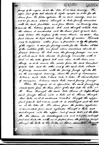
Specification of a patent for an Apparatus to be connected with, and to form part of, a Steam Engine Boiler. Granted to PHILO C. CURTIS, Utica, Ontario county, New York, May 3, 1831. MAKE a tub of about four feet in height, and two feet and four inches in diameter at the top, and two feet eight inches at the bottom. This is a suitable size for a high pressure ten horse power engine. This tub should have two heads, one at each end, and a partition about eighteen inches from the bottom of the tub. In the drawing annexed, the vessel marked A, exhibits the form of the tub. Within the tub, and between the upper end thereof and the said partition, place a strong tube with a calibre of about one and a fourth inches in diameter, and about sixty feet long, coiled similar to a common condensing worm for a distillery. One end of the tube passes through the upper part of the tub, and is firmly connected with the boiler; this part of the tube is marked B. The other end passes through the lower part of the tub above said partition, and is firmly connected with the forcing pump of the engine, as at the letter C on the drawing. The upper part of the tub should be tight, except an inlet, C, for the steam from the piston cylinder; and an outlet for the said steam through a tube firmly connected with the said partition, and from thence extending downwards towards the bottom of said tub; and through which tube the steam is conducted into the lower part of said tub, and below the surface of the water therein; as said lower part should be kept about half full of water. This water may be supplied either from a fountain, or by the operation of the engine, to serve for feeding water for the boiler. A tube of the calibre of the one first above mentioned, should be placed between the tub and the forcing pump, one end of which said tube should be firmly connected with a hole in the side of said tub, and near to the lower end thereof, so as to receive the water from the said lower part of the said tub; and the other end of said tube should be firmly connected with the forcing pump. Letter E on the drawing shows the point of connexion between the tube and the tub; and letter F shows the point of connexion between said tube and the forcing pump. When the engine is in operation, the forcing pump draws water from the lower part of the tub into the tube at E, thence it passes through the pump into a tube at C; thence through that tube as it is continued and coiled, through the upper part of said tub, and so on until it is discharged into the boiler through B. The steam from the piston cylinder is conducted from it through a tube and discharged into the upper part of the tub at the letter D; the steam so discharged fills the said upper part, and heats the water as it passes ses from the forcing pump through the tube into the boiler, as before described. From this upper part of the tub the steam passes into the lower part of VOL. VIII. No. 3. - SEPTEMBER, 1831. 24 1 BAKER'S Improvement in Medicine. said tub, through the tube of which mention has been before made; and from this part of the tub that part of the steam which remains uncondensed, passes off through another tube; which tube should be connected with the tub below the partition, and above the water in said lower part. The objects to be effected by the improvement and apparatus above described are, 1st. A reduction in the consumption of fuel for the boiler. This is done by giving to the water which is conveyed into said boiler, a very high temperature, on its passage through the coiled tube in the upper part of the tub. 2nd. This mode of supplying heat for the water in the boiler, is more regular than it could be if furnished by fuel alone; hence less attention to the furnace is required, and the generation and supply of steam from the boiler are more regular than in the ordinary mode. The object of the coiled tube is surface of sufficient size, which being exposed to the steam in the upper part of the tub, will allow the water in passing through said tube, time to acquire, very nearly, the temperature of the steam in the tub, and which, as the water is confined in the tube so that it cannot change into steam, is practicable. The water is thus raised in temperature much above boiling heat, and in that state passes into the boiler. The above described form I think the best calculated to produce the desired effects. The size of the apparatus must be varied in proportion to the capacity of the engine. to form a The combination of the above apparatus, and the application thereof to effect the objects above specified, are what I claim to have discovered and invented. PHILO C. CURTIS. Curtis' Steam Apparatus. B A D G EF
Published accounts: journal notice
Notice in the monthly list of patents, with remarks
Journal of the Franklin Institute, new ser., vol. 8 (1831), p. 175 · View the page
(See specification, p. 321, of our last volume.) 3. For an Apparatus to be connected with, and to form part of, a Steam Engine Boiler; Philo C. Curtis, Utica, Oneida county, New York, May 3.
Remarks. (See the specification.)
Published accounts: journal notice
Notice in the monthly list of patents, with remarks
Journal of the Franklin Institute, new ser., vol. 8 (1831), p. 184 · View the page
What I claim as my invention is the grinding, levelling, or polishing plates of copper, or other metals, or slabs of marble, stone, slate, glass, or any other material, by placing them upon a traversing bed, and operating upon them by means of revolving stones, grinders, buffs, and brushes, which revolving stones, &c. are fixed in a CURTIS' Steam Apparatus. frame to which a lateral vibratory motion is given; this lateral vibratory motion forming an essential part of my invention. J. W. STONE. Specification of a patent for an Apparatus to be connected with, and to form part of, a Steam Engine Boiler. Granted to PHILO C. CURTIS, Utica, Ontario county, New York, May 3, 1831.
Remarks. MAKE a tub of about four feet in height, and two feet and four inches in diameter at the top, and two feet eight inches at the bottom. This is a suitable size for a high pressure ten horse power engine. This tub should have two heads, one at each end, and a partition about eighteen inches from the bottom of the tub. In the drawing annexed, the vessel marked A, exhibits the form of the tub. Within the tub, and between the upper end thereof and the said partition, place a strong tube with a calibre of about one and a fourth inches in diameter, and about sixty feet long, coiled similar to a common condensing worm for a distillery. One end of the tube passes through the upper part of the tub, and is firmly connected with the boiler; this part of the tube is marked B. The other end passes through the lower part of the tub above said partition, and is firmly connected with the forcing pump of the engine, as at the letter C on the drawing. The upper part of the tub should be tight, except an inlet, C, for the steam from the piston cylinder; and an outlet for the said steam through a tube firmly connected with the said partition, and from thence extending downwards towards the bottom of said tub; and through which tube the steam is conducted into the lower part of said tub, and below the surface of the water therein; as said lower part should be kept about half full of water. This water may be supplied either from a fountain, or by the operation of the engine, to serve for feeding water for the boiler. A tube of the calibre of the one first above mentioned, should be placed between the tub and the forcing pump, one end of which said tube should be firmly connected with a hole in the side of said tub, and near to the lower end thereof, so as to receive the water from the said lower part of the said tub; and the other end of said tube should be firmly connected with the forcing pump. Letter E on the drawing shows the point of connexion between the tube and the tub; and letter F shows the point of connexion between said tube and the forcing pump. When the engine is in operation, the forcing pump draws water from the lower part of the tub into the tube at E, thence it passes through the pump into a tube at C; thence through that tube as it is continued and coiled, through the upper part of said tub, and so on until it is discharged into the boiler through B. The steam from the piston cylinder is conducted from it through a tube and discharged into the upper part of the tub at the letter D; the steam so discharged fills the said upper part, and heats the water as it passes ses from the forcing pump through the tube into the boiler, as before described. From this upper part of the tub the steam passes into the lower part of VOL. VIII. No. 3. - SEPTEMBER, 1831. 24 1 BAKER'S Improvement in Medicine. said tub, through the tube of which mention has been before made; and from this part of the tub that part of the steam which remains uncondensed, passes off through another tube; which tube should be connected with the tub below the partition, and above the water in said lower part.
About this record
- Patentee
- DATAMP
- Date
- the Name and Date index of patents, DATAMP, USPTO records
- Invention
- DATAMP
- Listed in
- the Name and Date index of patents, DATAMP, USPTO records, Jim Shaw's X-patent list, the Journal of the Franklin Institute, Burke's List of Patents (1847)
- in_burke