

Drawings and documents
National Archives restored drawings: drawing
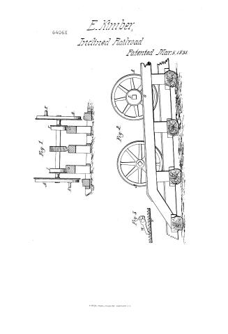
Emmor Kimber's Patent Drawing for Locomotive Carriages and Rails

National Archives, Restored Patent Drawings (Record Group 241) · Full-size scan at the National Archives · Catalog record
Text on the drawing
Words on the drawing as machine-read by the National Archives; not checked. Useful mainly for searching.
101. RAILWAYS. / 1 THE "WAY." / [120] Inclined Planes. / 62 / CLASSIFICATION / EMMOR KIMBER / 6406-X / LOCOMOTIVE CARRIAGES & RAILS / DIVISION. / Patented March 5th 1831. / Fig. 1. / L:L / FL / Fig2. / Fig 3. / marmi / said about mountry sail 0 / REFERERENCES / Fig 1. End view of the rails with the force axle and wheels / Fig2 Side viewof do: with a fore and hind wheel. / Fie 3. Part of the Cog-rail detached. / À Common ivbeels of a Locomotive carriage. / E, Wrist 07 Crank / Small wheels for ascending acclivities / 0 Rails for the small wheels / U Coo-rail / W Pawle / S Cop. Coq-ivbeet wheel
USPTO scan
The patent as scanned by the USPTO
-
 Page 1
-
 Page 2
-
 Page 3


U.S. Patent and Trademark Office · Google Patents
Published accounts: specification
Specification printed in the Journal of the Franklin Institute
Journal of the Franklin Institute, new ser., vol. 8 (1831), p. 22 · View the page
Text of the specification as printed in the Journal, from OCR; not proofread.
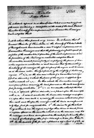
Specification of a patent for Locomotive Carriages, and Rail-roads adapted thereto. Granted to EmMOR KIMBER, Kimberton, Chester county, Pennsylvania, March 5, 1831. The invention consists principally in employing the power of locomotive engines on acclivities, in such manner, that by diminishing the velocity of its carriage, the effective force of the engine will be increased in the same ratio-thereby superseding the necessity of stationary engines. Fig. 1. A I S IC I A, A, Fig. 1st and 2nd, are the common wheels of a locomotive carriage, (3 feet in diameter,) to which the power of the engine is applied, by a wrist or crank at E, E. On these wheels the locomotive carriage runs upon a plane, drawing the train forward on the rails, nearly nine feet for every evolution. I, I, are two smaller wheels, (attached to A, A, or separate,) 1 foot in diameter, and placed upon the same axle with A, A. To ascend acclivities the locomotive carriage runs upon I, I, upon their own rails, O, O, raising the common wheels clear from their rails, and therefore the carriage with the train moves forward only three feet for every revolution. The diameter of the wheels, being as three to one, the engine employs three times as much power in a given space on the smaller wheels, as on the common ones-but the carriage and train move forward on the rails proportionably slower, and so of wheels of any other proportions, as four to one, five to one, &c. On the middle of the fore axle is placed a cog wheel, S, of like diameter with the smaller wheels, to work free in the cog rail, U, to prevent slipping on great ascents. This use of the cog wheel is DAWLEY'S Machine for Cutting Leather. known and has been variously proposed and tried. The improvement consists in substituting one cog wheel and its rail in the centre, in the stead of mixed rails, and cog wheels on both sides of locomotive carriages. W, on Fig. 2, is a drag, or pall, that may be attached to locomotive carriages, and every car in their train to work upon the cog rail, U. Its use is well known to prevent a slip or slide in cases of accidents on great acclivities, but it derives new importance from its connexion with the cog rail, U, elevated in the middle of the road. The ascending rails, O, O, and U, may be so constructed, as to rest upon the foundations with the common rails, and be raised to their proper height by blocks: they are only used in ascending acclivities, and for the small wheels. The hind wheels of the locomotive carriage, and the wheels of all the cars in the train, run on the common rails. In this specification the wheels on the fore axle only are mentioned, because the power is considered as applied to the fore wheels. If the power should be applied to the hind wheels instead, or in part on both fore and hind, the principle would not thereby be changed. The small additional wheels on either, or on both, would be the application of power described and claimed as my invention. EMMOR KIMBER. Side View of Kimber's Rail-way and Carriage. Fig. 2. Abstract of the specification of a patent for a Machine for Splitting, Shaving, and Cutting Leather, Skins, and other substances. Granted to AUGUSTUS S. DAWLEY, Boston, Massachusetts, March 22, 1831. THIS improvement rests upon a combination of machinery in a manner new and hitherto unused, to effect with ease, precision, and rapidity, the shaving, splitting, or cutting of leather, skins, and other substances, in any desired thickness, breadth, and length. Every piece of the machinery used in this invention may have been used before separately, and for other purposes, and the combination only is here claimed. DAWLEY'S Machine for Cutting Leather. @ Fig. 1. B D F K M f B F C Fig. 1, in the drawing, is a perpendicular view of the machine in its place, as fitted for operation. Fig. 2, is a view of the back side of it. Fig. 3, is a section cut from front to rear at the place marked f, f, Fig. 1. A, Figs. 2 and 3, is a bed-plate, of cast iron, increased in At thickness towards its centre, to double the thickness of the other parts, in order to give it the strength necessary for the bearing of the screw by which the moving plate is moved on its pivots. each end of the bed-plate is a screw hole, a, a, Fig. 1, to fasten the machine to a block or table. Fig. 2. e FB B, B, Figs. 1 and 2, are upright shoulders, on plates running across to sustain the machinery. C, Figs. 1, 2, and 3, is a polished wrought iron roller, turning freely on its axis, and supported by B, B. This serves as a gauge to regulate the thickness to which the leather or skin is intended to be cut. Its bearings may be so regulated that the roller may be brought nearer to, or removed farther from the edge of the knife at pleasure. M Fig. 3. D, Figs. 1 and 3, is the knife, or cut•ting plate, fastened by nuts b, b, its edge resting nearly under the centre of the roller C. E. Figs. 1 and 3, is the moveable plate, made as strong as the bed-plate. F, F, Figs. 1 and 2, are two shoulders, or upright plates on E, and of the same thickness and width; they lie within the upright plates on the bed-plate, and are fastened to them by the pivots c, c, Fig. 1. The shoulders of the moving plate move on their pivots to the extent required to vary the position of the edge of the knife. The motion of the moving plate and knife are effected by means of the screw J, and the spring I. C, on Figs. 2 and 3, represents the shaving plate; its use is to guide the water part of the skin which is cut off, obliquely down from the edge of the knife. The front of the shaving plate, where it rests on the moveable plate, is secured to the shoulders on the moving plate by pivots, d, d, Fig. 1, on which pivots it turns freely. Its junction is shown also at d, Fig. 3. The back part of the shaving plate is nearly a square bar, and is supported by the spring, H, as seen in LINNELL'S mode of Mixing Paint. Fig. 2. The leather to be cut enters between this bar and the roller, as seen Fig. 3. The springs H and I, are fastened to the bed-plate by a rivet, shown at e, Fig. 2. The spring H must have sufficient strength to sustain the C against the skin to be cut, so as to keep it against the roller. The knife is graduated by means of the spring I, and the screw J. That screw passes through a hole tapped in the lip K, Figs. 1 and 3. The lips, K and L, which are projections from the bed-plate and moveable plate, are depressed, or sloped downward, for the purpose of permitting the strip of leather, and shaving, to pass freely over the screw. M, is a wooden handle at the end of the lip on the moveable plate, for convenience in handling the machine. The leather introduced between C and G may be drawn through in any convenient mode. It will be observed by inspecting the machine, that the knife plate is so fastened that it is impossible for it to slip back; and as the edge of the knife wears away, the screws or nuts are readily so adjusted that the edge may be brought into the desired position by sliding the plate towards the collar, and the arrangement for thus easily changing the position of the edge of the knife, is also an advantage over the former mode of fixing the knife in shaving or cutting machines.
Published accounts: journal notice
Notice in the monthly list of patents, with remarks
Journal of the Franklin Institute, new ser., vol. 8 (1831), p. 9 · View the page
5. For an improvement in Locomotive Carriages, and Rails adapted thereto; Emmor Kimber, Kimberton, Chester county, Pennsylvania, March 5.
Remarks. (See the specification.)
Published accounts: journal notice
Notice in the monthly list of patents
Journal of the Franklin Institute, new ser., vol. 8 (1831), p. 21 · View the page
THE essential character of the invention consists in adapting the argand burner to lamps with imperforate bottoms. To effect this, a cylindrical tube is constructed concentric with, and interior to, the wick, destined to convey the current of air through its centre, and this tube is furnished with a spiral groove upon its exterior surface, for the purpose of raising or depressing the wick, by a revolution of the tube which contains it, in precisely the same manner as the common argand lamp. The air tube, however, instead of terminating in an orifice at the bottom of the lamp, receives its current of air through a channel which opens beside the wick, at the top of the lamp. The channel is furnished in either of the following methods. In the first the interior, or air tube, is to be enclosed in a second, which is concentric with it, and so much larger, that the intermediate space is sufficient for the reception of the wick and the moveable tube which contains it. This tube, as it is enclosed by a third, or exterior tube, may, for the convenience of description, be called the middle tube. The exterior tube is so much larger than the middle one, that the space between them is equal to, or greater than the capacity of the interior tube, so that the descending current of air, which passes through this space, furnishes a supply to the interior tube through which it ascends, as in the common argand lamp. The exterior tube is closed at the bottom, but descends far enough below the other to leave room for the current of air which passes around under the space between the middle and interior tube, and this space, which, as before remarked, contains the wick, is closed at the bottom by a circular zone, so as to prevent all communication between the air passage and the oil that supplies the wick. To supply the wick with oil, one or more tubes pass across the air passage, opening upon the inside of the middle, and outside of the exterior tube, to which tubes they are fastened by solder. According to the second plan proposed for admitting the atmosphere to the bottom, the air tube itself is constructed just as before, except that it is closed at the bottom. The descending current of air is thus furnished by one or more tubes, which pass down by the side of the wick from the top of the lamp, and enter the bottom of the tube, to which they are joined by solder. KIMBER'S Locomotive Carriages. Gallup's Improved In both these cases, the ascending current of air Lamp. 000000 a 00000 C a which supplies the exterior of the flame, passes through a circular row of perforations in the flanch which supports the chimney of the lamp as in the common argand burner, and an air hole made through the lamp, or cylinder flanch, to let the air into the oil which surrounds the outer cylinder, or on the common argand principle. LEWIS F. GALLUP. a, spiral tube interior to the wick. b, space for the wick. c, space for air to pass to the interior tube. d, pipe for admitting air to the wick. Specification of a patent for Locomotive Carriages, and Rail-roads adapted thereto. Granted to EmMOR KIMBER, Kimberton, Chester county, Pennsylvania, March 5, 1831.
About this record
- Patentee
- DATAMP
- Date
- the Name and Date index of patents, DATAMP, USPTO records
- Invention
- DATAMP
- Listed in
- the Name and Date index of patents, DATAMP, USPTO records, Jim Shaw's X-patent list, the Journal of the Franklin Institute, Burke's List of Patents (1847)
- in_burke