

Drawings and documents
National Archives restored drawings: drawing
James Clarke's Patent Drawing for a Self-Regulating Conduit

National Archives, Restored Patent Drawings (Record Group 241) · Full-size scan at the National Archives · Catalog record
Text on the drawing
Words on the drawing as machine-read by the National Archives; not checked. Useful mainly for searching.
61. / 6. HYDRAULIC ENGINEERING / [8 / Canals, Look Gates, / CLASSIFICATION / 6349-x / James Clarhi / DIVISION. / Self regulating conduit / 25 / Patented / References / the conduit / 40d / the gate / sezens / aire box oc flost box / Patent office 11th Aug 1838 / Madi under the direction of the Commision / of Patents in conformity armity with act 3d March 1837. / Munsh Sumooth
USPTO scan
The patent as scanned by the USPTO
-
 Page 1
-
 Page 2
-
 Page 3
-
 Page 4


U.S. Patent and Trademark Office · Google Patents
Published accounts: specification
Specification printed in the Journal of the Franklin Institute
Journal of the Franklin Institute, new ser., vol. 7 (1831), p. 318 · View the page
Text of the specification as printed in the Journal, from OCR; not proofread.
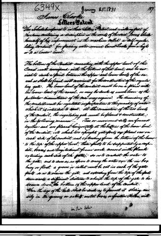
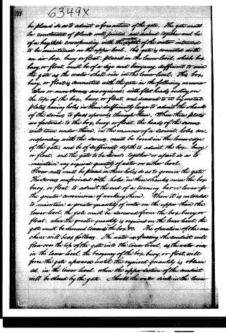
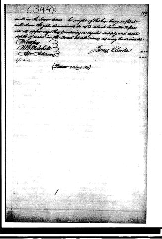
Specification of a patent for a machine called the Self-regulating Conduit; for passing water around canal locks, from a higher to a lower level. Granted to JAMES CLARKE, Westmoreland county, Pennsylvania, January 25,1831. THE bottom of the conduit, connecting with the upper level of the canal, must correspond with the bottom of that level, and be carried to such a point between the upper and lower levels of the canal as shall be found most convenient for the construction of the regulating gate; the lower level of the conduit must be on a plane with the lower level of the canal, or may be sunk as much lower as the particular circumstances of the case may require. The dimensions of the conduit must be regulated in proportion to the quantity of water which it is intended to vent. At the connexion of the two levels of the conduit, the regulating gate must be placed, and constructed in the following manner. Two, or more, mud sills are framed together, and are placed horizontally at the bottom of the lower level of the conduit, into which two upright gate posts are placed, one on each side of the conduit, and extending from the bottom of the lower to the top of the upper level; these posts to be supported by a cap sill, braces, and longitudinal frame work, covered with plank extending each side of the gate, so as to conduct the water towards the gate, and to serve as an apron to convey the water over the air box, buoy, or float. A groove or rebate must be cut in each of the gate posts, so as to receive the gate, and extending from the top of the posts downwards, a sufficient distance, to admit the top of the gate to be drawn down to the bottom of the upper level of the conduit. When the size of the gate shall be such as to prevent it sliding easily in the grooves, CLARKE'S Self-regulating Conduit. or rebates, metals, boxes, or friction rollers, will be placed so as to admit a free action of the gate. The gate must be constructed of plank well jointed and secured together, and be of a height corresponding with the greatest depth of water intended to be maintained on the upper level. This gate is connected with an air box, buoy, or float, placed in the lower level, which box, buoy, or float, must be of a size and buoyancy sufficient to raise the gate as the water shall rise in the lower level. This box, buoy, or float, is connected with the gate in the following manner. Two, or more, screws, are required with flat heads, resting on the top of the box, buoy, or float, and secured to it by metal plates, having holes in them sufficiently large to admit the shank of the screw to pass upwards through them. When these plates are fastened to the box, buoy, or float, the heads of the screws will turn under them in the manner of a swivel. Holes corresponding with the screws must be bored in the lower edge of the gate, and be of sufficient depth to admit the box, buoy, or float, and the gate to be screwed together, or apart, so as to maintain any required quantity of water on either level. Screw nuts must be placed in these holes so as to govern the gate. The screws are provided with holes in their shanks, near the box, buoy, or float, to admit the end of a turning bar or lever, for the greater convenience of working them. When it is intended to maintain a greater quantity of water on the upper than the lower level, the gate must be screwed from the box, buoy, or float; when the greater quantity is required on the lower level, the gate must be screwed towards the box, &c. The operation of the machine will be as follows. The water, in passing the conduit, will flow over the top of the gate into the lower level; as the water rises in the lower level, the buoyancy of the box, buoy, or float, will force the gate upwards until the required quantity is obtained in the lower level, when the upper section of the conduit will be closed by the gate. Should the water sink in the lower level, the weight of the box, buoy, or float, will draw the gate downwards, so as to admit the water to pass over its upper edge, thus producing a regular supply, and such depth of water in the canal, at all times, as may be desirable. E A D C D C B A, regulating gate. air box. C, C, screws. D, D, gate posts. E, cap sill. F, mud sill. JAMES CLARKE.
Published accounts: journal notice
Notice in the monthly list of patents, with remarks
Journal of the Franklin Institute, new ser., vol. 7 (1831), p. 313 · View the page
36. For a machine called the Self-regulating Conduit, for passing water around canal locks, from a higher to a lower level; James Clark, Westmoreland county, Pennsylvania, January 25.
Remarks. (See the specification.)
Published accounts: journal notice
Notice in the monthly list of patents, with remarks
Journal of the Franklin Institute, new ser., vol. 7 (1831), p. 318 · View the page
Specification of a patent for a machine called the Self-regulating Conduit; for passing water around canal locks, from a higher to a lower level. Granted to JAMES CLARKE, Westmoreland county, Pennsylvania, January 25,1831.
Remarks. THE bottom of the conduit, connecting with the upper level of the canal, must correspond with the bottom of that level, and be carried to such a point between the upper and lower levels of the canal as shall be found most convenient for the construction of the regulating gate; the lower level of the conduit must be on a plane with the lower level of the canal, or may be sunk as much lower as the particular circumstances of the case may require. The dimensions of the conduit must be regulated in proportion to the quantity of water which it is intended to vent. At the connexion of the two levels of the conduit, the regulating gate must be placed, and constructed in the following manner. Two, or more, mud sills are framed together, and are placed horizontally at the bottom of the lower level of the conduit, into which two upright gate posts are placed, one on each side of the conduit, and extending from the bottom of the lower to the top of the upper level; these posts to be supported by a cap sill, braces, and longitudinal frame work, covered with plank extending each side of the gate, so as to conduct the water towards the gate, and to serve as an apron to convey the water over the air box, buoy, or float. A groove or rebate must be cut in each of the gate posts, so as to receive the gate, and extending from the top of the posts downwards, a sufficient distance, to admit the top of the gate to be drawn down to the bottom of the upper level of the conduit. When the size of the gate shall be such as to prevent it sliding easily in the grooves, CLARKE'S Self-regulating Conduit. or rebates, metals, boxes, or friction rollers, will be placed so as to admit a free action of the gate.
About this record
- Patentee
- DATAMP
- Date
- the Name and Date index of patents, DATAMP, USPTO records
- Invention
- DATAMP
- Listed in
- the Name and Date index of patents, DATAMP, USPTO records, Jim Shaw's X-patent list, the Journal of the Franklin Institute, Burke's List of Patents (1847)
- The Franklin Institute's journal spells the name differently.
- in_burke