

Drawings and documents
National Archives restored drawings: drawing
Jacob Perkin's Patent Drawing for a Paddle Wheels

National Archives, Restored Patent Drawings (Record Group 241) · Full-size scan at the National Archives · Catalog record
Text on the drawing
Words on the drawing as machine-read by the National Archives; not checked. Useful mainly for searching.
$350 / PROPULSION / thing / Driving. / facob Porkins / Vol.8.373. / and / Paddle Wheels, / Patented 30. Nov 1829. / Figh3. / 5733-+ + / Fig.1. / Fig.2. / OIRI / References. Ref rences. / Fig1 side of ship.showing paddle projecting / from bow. Eig.2.top view A position of pacidles / Patent Office 3/Aug/ 841 / in bow. B.stearn padales. Eg.3. top view / paddles projecting f romsides, / Made under the direction of the Commision of Patients / in con informity with act of bougrep 3. March 1837, / Commipioner of Fatuly,
USPTO scan
The patent as scanned by the USPTO
-
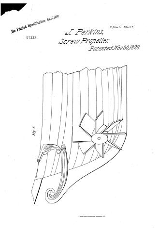 Page 1
-
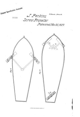 Page 2
-
 Page 3


U.S. Patent and Trademark Office · Google Patents
Published accounts: journal notice
Notice in the monthly list of patents, with remarks
Journal of the Franklin Institute, new ser., vol. 5 (1830), p. 140 · View the page
37. For an improved Paddle for Propelling Steam and other Vessels; Jacob Perkins, Civil Engineer, a citizen of the United States, but now of London, in England, November 30.
Remarks. We have already published some observations upon Mr. Perkins' paddle wheel, and will, in an early number, give the specification with engravings. FOR THE JOURNAL OF THE FRANKLIN INSTITUTE. On the power required to propel Carriages on Rail-roads, compared with that for moving boats in Canals. By JAMES P. ESPY. THERE is not, I believe, any subject connected with the arts which presents higher claims to public attention than that of rail-roads; a subject which has been recently treated in an able and perspicuous manner, in a work which deserves to be most particularly recommended to the notice of practical men; the "Rail-road Manual, or a brief exposition of principles and deductions, applicable in tracing the route of a rail-road. By S. H. Long, Baltimore, Lieut. Col. Engineers, in the service of the Baltimore and Ohio Rail-road Company." In two neat little volumes, published in Baltimore, in September last. The talents, the practical acquirements, and the zeal of Col. Long in the public service, are too well known to need any eulogium from me. Every one desirous of information respecting rail-roads, should consult this work; there is one point respecting these structures, which ought to be pressed again and again on the attention of the public, until they are fully aware of the immense advantages rail-roads offer over every other mode of conveyance. It is known to men of science, that it has been proved, by the most unexceptionable experiments, that the friction of a carriage on a well constructed rail-road, is not increased with an increased velocity; or, in other words, that the tension of a rope with which a Comparison between Rail-roads and Canals. carriage on a rail-road is drawn at one time, with a uniform velocity of 20 feet per second, at another with a uniform velocity of 40 or 100 feet per second, is the same; whilst the tension of a rope drawing a canal boat is 4 times as great with a double velocity, 9 times as great with a triple velocity, and 100 times as great for 10 times the velocity, and, indeed, a little greater, as is clearly shown by some very late and beautiful experiments by Mr. Walker, detailed in the last volume of the Transactions of the Royal Philosophical Society; that is, the resistance increases in a higher ratio than that of the square of the velocity. Now it has been shown by Mr. Wood, (in his work on canals and rail-roads,) that the resistances on canals and rail-roads are equal, with a velocity of 3 miles an hour; amounting to about one pound of resistance for every 200 pounds of load: and, according to this ratio, he has calculated, that with a velocity of 6 miles an hour, 3 times as many horses would be required to do the same quantity of work on a canal, which would be required on a rail-road. But, when the new rail-road carriage, invented by Winans, shall be introduced, the resistance may be fairly calculated not to exceed one pound to a thousand, or one-fifth of the quantity allowed by Mr. Wood, According to this ratio, the resistance on a canal would be equal to that on a rail-road, with a velocity on the former of 1f mile per hour; a double velocity, or 34 miles per hour, will give four times the resistance on the canal; ten times the velocity, or 16 miles, will give 100 times the resistance; and 20 times the velocity, or 32 miles, (the greatest velocity which locomotive engines have been made to move in Great Britain, would give the enormous resistance of 400 times, in favour of rail-roads. And this is calculated on the supposition that the resistance on canals increases only in proportion to the squares of the velocities, when, in fact, (especially if the canal is narrow and shallow,) it increases in a higher ratio, whilst that on rail-roads is the same at all velocities.
Published accounts: journal notice
Notice in the monthly list of patents
Journal of the Franklin Institute, new ser., vol. 5 (1830), p. 381 · View the page
A further benefit claimed in the framed beam, is its use for supportPERKINS' Paddle for Propelling Vessels. ing the roofs of houses or public buildings; by which a room of one or two hundred feet can be roofed without other supports than the walls. A model ten feet long, 18 inches high, of 14 inch cypress timbers, supported fourteen men, whose weight amounted to 2140 lb. مل GEORGE W. LONG. Fig. 1. T T 本 B A B PB P B P B P S 2 2 i 2 PLAN OF THE ELIPTICAL FRAME BRIDGE. Explanations of the above plan. Fig. 1 is a side view of the bridge. Fig. 2 is a vertical section through the centre posts. S, S, &c. are strings, Figs. 1 and 2. P, P, &c. are posts, Figs. 1 and 2. i, i, &c. Straps of iron attaching the posts to the strings, Figs. 1 and 2. B, B, &c. are the main braces, Fig. 1. T, T, &c. timbers bracing the heads of the posts apart, Fig. 1. L, the sill of the bridge, Fig. 2. s, s, &c. are the sleepers, Figs. 1 and 2. F, is the flooring. b t P P Fig. 2. b L A, a joint in the string secured by straps of iron well bolted to the timbers, Fig. 1. b, b, braces. tcross piece to steady the frame, Fig. 2. Specification of a patent for a new and improved Paddle for Propelling Steam and other Vessels. Granted to JACOB PERKINS, Esq. Civil Engineer: a citizen of the United States, formerly residing in the City of Philadelphia, but now of the City of London, in England, November 30, 1829.
About this record
- Patentee
- the Journal of the Franklin Institute, Journal
- Date
- the Name and Date index of patents, USPTO records, Jim Shaw's X-patent list
- Invention
- the Name and Date index of patents
- Listed in
- the Name and Date index of patents, USPTO records, Jim Shaw's X-patent list, the Journal of the Franklin Institute, Burke's List of Patents (1847)
- The patentee's full name comes from the Franklin Institute's journal.
- in_burke
- burke_date_differs
- residence_from_burke