

Drawings and documents
National Archives restored drawings: drawing
John C. Ely's Patent Drawing for a Screw Dock

National Archives, Restored Patent Drawings (Record Group 241) · Full-size scan at the National Archives · Catalog record
Show the text on the drawing Hide (30 words)
Words on the drawing as machine-read by the National Archives; not checked. Useful mainly for searching.
01. / 1. / HYDRAWLIC ENGINEERING / DocksiLiting / John Elu / CLASSIF ISATION / 5351-4 / ISION / SREW DOCK / Patented January 28 1829. / SIR
USPTO scan
The patent as scanned by the USPTO
-
 Page 1
-
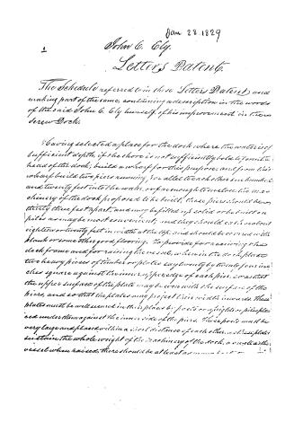 Page 2
-
 Page 3
-
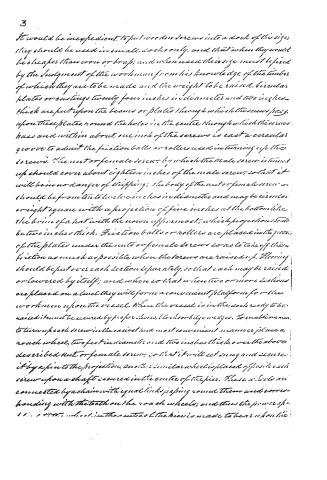 Page 4
-
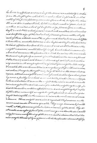 Page 5
-
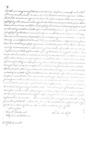 Page 6


U.S. Patent and Trademark Office · Google Patents
Show the transcription Hide (1,875 words)
Machine transcription (LightOnOCR) of the pages as scanned by the USPTO, most of them the handwritten copies made when the records were restored after the 1836 fire. Not checked; it can misread handwriting, so compare it with the scan.
Page 1.
405-3
OR X SR
5,351
5351X
J.T. Ely,
Dock,
Patented Jan. 28, 1829.

Page 2.
Jan 28, 1829
John G. Ely.
Letters Patent.
The Schedule referred to in these Letters Patent, and making part of the same, containing a description in the words of the said John G. Ely himself, of his improvement in the Screw-Dock.
Having selected a place for the dock where the water is of sufficient depth, if the shore is not sufficiently solid to form the head of the dock; build a wharf for this purpose, and from this wharf build two piers running, as called to each other such number and twenty feet into the water, or far enough to enclose the machinery of the dock proposed to be built; these piers should be thirty-three feet apart, and may be filled up solid or be built on piles as may be most convenient; and they should each contain eighteen or twenty feet in width at the top, and should be covered with plank or some other good flooring. To provide for receiving the dock frame and for raising the vessel, when in the dock, place two heavy pieces of timber or plates eight or twenty by twenty-four inches square against the inner side of the edge of each pier, so as that the upper surface of the plate may be even with the surface of the piers, and so that the plates may project their width inward. These plates must be well secured in their places by posts or uprights or piles placed underneath against the inner side of the piers. These posts must be very large and placed within a short distance of each other, so that they sustain the whole weight of the machinery of the dock, and the vessel when raised. There should be at least as many as
Page 3.
raised her keel rests on these sections and crosses them in their centre at right angles. Each section is composed of four pieces of strong, firm timber thirty-five feet long and should be eighteen inches square. The two upper pieces are placed directly over and about two feet above the two under pieces, and parallel to each other leaving a space between the timbers sufficiently wide to admit the screw. The upper and lower timbers are fastened together by posts at the end, and braced from the ends to the centre in such a manner as to sustain the greatest possible weight. The object of forming these sections in this manner with two timbers one over the other, is to enable the workman to secure them by the common method of bracing and bolting in such a manner as to sustain the weight of the heaviest ships without yielding or springing. These sections are suspended in the dock from the plates above described with two screws passing through said plates down through the ends of each section in such a manner that the sections will lie parallel to and at equal distances from each other, and at right angles with the plates or sides of the dock. The screws may be secured in the ends of the sections by keys passing through them or by a female screw-nut or casting of sufficient size to sustain the sections, otherwise it is intended to use the dock for taking in steamboats the screws should be secured in the ends of the sections by a female screw-nut or casting so as to let the screw pass through far enough to admit a steam boat into the dock, with the guards of the boat clear above the plates of the dock; this is done by passing the screw so far through the female screws in the sections as to prevent the tips or heads of the screws from coming in contact with the guard of the boat when raising it. The screws may be of wood, iron, or brass. Wood screws will do very well for small docks, but iron or brass are better for large docks. For a dock of sufficient size and strength to raise a ship of five hundred tons, which is the one proposed
Page 4.
3
It would be inexpedient to put wooden screws into a dock of this size; they should be used in small docks only, and that when they would be cheaper than iron or brass; and when used their size must be fixed by the judgment of the workman from his knowledge of the timbers of which they are to be made and the weight to be raised. Circular plates or castings twenty-four inches in diameter and two inches thick are put upon the beams or plates through which the screws pass. Upon these plates, round the holes in the centre through which the screws pass and within about one inch of the screws is cast a circular groove to admit the friction balls or rollers used in turning up the screws. The nut or female screw, by which the male screw is turned up should cover about eighteen inches of the male screw, so that it will be in no danger of slipping; the body of the nut or female screw should be from ten to twelve inches in diameter and may be circular or right square with a projection of five inches at the bottom like the brim of a hat with the crown up as most; which projection should be two inches thick. Friction balls or rollers are placed in the grooves of the plates under the nuts or female screws so as to take off the friction as much as possible when the screws are raised up. Flooring should be put over each section separately, so that each may be raised or lowered by itself; and when so that when two or more sections are placed on a level they will form a convenient platform for the workmen upon the vessel. When the vessel is in the dock ready to be raised it must be secured by proper shores, blocks or bite wedges. To enable men to turn up each screw in the easiest and most convenient manner place a round wheel, two feet in diameter and two inches thick, over the above described nut or female screw, so that it will set snug and secure it by a pin to the projection. Another similar wheel is placed opposite each screw upon a shaft secured in the centre of the pier. These wheels are connected by a chain with equal links passing round them and corresponding with the teeth on the noach wheels; and thus the power of 11... is to the wheel in the centre of the pier is made to bear upon the
Page 5.
he lever is applied and can keep the screw constantly in motion from the shaft upon which the reach-wheel is placed, in the midst of the pier place a common spur wheel, two feet in diameter and two inches thick; let this wheel mesh or gear into another similar wheel of half the size, placed upon another shaft, and let this wheel gear or mesh into another similar wheel and half the size of the last wheel, placed upon another shaft. Each of these wheels must be so formed that a lever can be applied to turn them, and the labourer when he finds the first wheel turns too hard applies his lever to the second and so to the third as the weight increases, until the ship is up. Each wheel increases his power but decreases the speed with which he raises the screw when the screw is properly secured upon the deck, the men are placed to the screws and each screw is turned up so that each section may sustain its due proportion of the ship's weight while raising. To enable the workmen to raise a very heavy ship with more ease, and when it may be thought necessary to relieve the screws in some degree, attach a weight to each end of each section by a chain passing over a pulley or wheel, secured to the plates above with proper hooks and catches to secure the weight to the chain and to secure the chain in any position desired, and so fix that the weight may be easily applied to the section or taken off at pleasure. Each weight may be from five to fifteen tons, more or less, as may be thought expedient; and as it may be thought advisable in the manner to relieve the workmen and ease the screws. These weights serve also to regulate the pressure on the screws and render it more equal. They may, however, be provided not, at the pleasure of the builder or owner of the deck. They do not make a necessary part of the machine any more than the above described ring for more easily turning up the screws; as it is obvious that the screws may be turned up by any power which the operator chooses to apply.
Page 6.
5
I do not claim any one of the several minor improvements which I have made in it, and which I believe to be my invention, but I do claim as my invention the above described method of applying the screws whereby the sections are suspended upon the screws and are not forced up by the screws having a form cast or bearing under water upon which they are set. By the above method of applying the screw invented by me as the brass screw is any harder on the screws, the part of the screw exposed to water is not so thereby much liable to break. There are other advantages arising from this new method of applying a screw in the screw docks which will be easily discovered on examining the docks. I further claim as my improvement the application of weights to the raising of boats in a screw dock as above described acting in combination with the screw. I further claim as my improvement the above described method of so adjusting and preparing the sections by passing the male screws through the female screws placed at the ends of the sections as that steam boat with her gear and all her machinery in maybe taken into a dock of a width sufficient to receive her hull. I further claim as my improvement, the above combination of wheels and chains and gearing so as to enable a man by one continued motion in a circle around the wheel on which the bars is placed, to raise the screw to which the gearing is attached. The above specification is not compared with drawings which will yet be and more distinctly describe the different parts of the docks and to which references is made. It is our hope to improve every day. I give it a patent. I am willing you have this twenty second day of December eighteen hundred and seventy eight.
Witnesses
Geo. C. Leonard
Stephen C. Williams
John C. Gyp.
2170 Words.
Published accounts: journal notice
Notice in the monthly list of patents
Journal of the Franklin Institute, new ser., vol. 3 (1829), p. 432 · View the page
Preparing white lead for painting, 2. Drying cut tobacco, 3. Washing machine, 4. Thrashing machine, 5. Measure for cutting clothes, 6. Combs of wood, &c. 7. Prairie bogging and ditching plough, 8. Cleaning paper rags, 9. Supplying water to water wheels, 10. Manufacture of salt, 11. Improved press, 12. Mill for grinding apples, 13. Washing machine, 14. Spinning wool and cotton, 15. Hanging forge hammers, 197 Paulus Hedl, ib. Matthew D. Brown, 198 Harvey Paign, ib. Townsend Carpenter, ib. Samuel A. Brounson, 199 William Woodworth, ib. James R. Nance, 200 Abel Bayrd, ib. Silas Lawson, ib. John Butterworth, 201 Joseph Woodhull, ib. John Davidson, ib. John Thorp, 202 John Barney, George Campbell, Reuben Mosher, 254 255 ib. James S. Wood, ib. Levi Peterson, 256 Samuel Lambert, ib. John Gordon, ib. William Debit, 257 John Haughton, ib. J. A. Teissier, 258 T. Bakewell and J. P. Bakewell, ib. David D. Demarest, ib. Amos Larcom, ib. Nathaniel Harris, 259 Jonathan M'Neal, 260 16. Conical, steel, grist mill, Thomas Baker, ib. 17. Razor strap, 18. Hulling cotton seed, 19. Compound lever press, 20. Cure of inflected spine, 21. Blanks for checks, 22. Improvement in spinning, 23. Straightening and soldering drums, 24. "Forcing, valve, piston churn," 25. Planting of corn, 26. Cutting sausage meat, 27. Manufacture of shoe pegs, J. W. Osborn, Francis Follet, ib. ib. John Rodgers, 261 James K. Casey, ib. James Atwater, ib. John Thorp, 262 &c. Luke N. Perry, ib. Benjamin Cushwa, 263 *Lennox, Croft, and Pitner, Elias Wade, ib. ib. S. S., jr., and E. Beckwith, Calvin Perkins, 264 28. 29. Screw docks, forks, John C. Ely, ib. ib. Index. PAGE 30. Cutting wafers, and leather for gloves, Elisha Mills Ely, 31. Machine for breaking sugar, 33. Cooking furnaces and ovens, 32. Canal and other boats, 34. Spinning yarn, 35. Water, and air proof cement, &c. 36. Manufacture of cider, 37. Grist mill, February. 1.
About this record
- Patentee
- Jim Shaw's X-patent list
- Date
- the Name and Date index of patents, USPTO records, Jim Shaw's X-patent list
- Invention
- the Name and Date index of patents
- Listed in
- the Name and Date index of patents, USPTO records, Jim Shaw's X-patent list, the Journal of the Franklin Institute, Burke's List of Patents (1847)
- The Franklin Institute's journal gives a different date.
- Burke's 1847 Patent Office list gives the same patent.