

Drawings and documents
USPTO scan
The patent as scanned by the USPTO
-
 Page 1
-
 Page 2
-
 Page 3
-
 Page 4


U.S. Patent and Trademark Office · Google Patents
Show the transcription Hide (623 words)
Machine transcription (LightOnOCR) of the pages as scanned by the USPTO, most of them the handwritten copies made when the records were restored after the 1836 fire. Not checked; it can misread handwriting, so compare it with the scan.
Page 2.
United States Patent
Patent No.: X5344
John Thorp
Letters Patent.
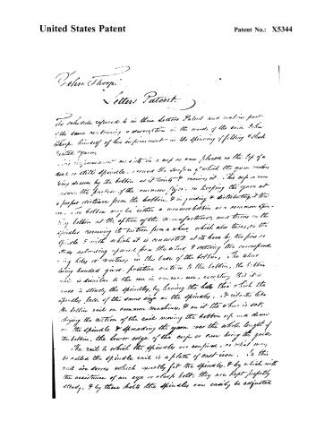
The schedule referred to in these Letters Patent and making part of the same containing a description in the words of the said John Thorp, himself of his improvement in the spinning of filling & flax twisted yarn.
This improvement consists in a cup or can placed on the top of a deal or still spindle, around the surface of which the yarn is being drawn by the bobbin as it twists & receives it. This cup or can serves the purpose of the common flyer, in keeping the yarn at a proper distance from the bobbin, & in guiding & distributing it thereon. The bobbin may be either a weavers bobbin or a common spinning bobbin at the option of the manufacturer, and turns on the spindle receiving its motion from a wheel which also turns on the spindle & with which it is connected at its base by two pins or studs extending upward from the wheel & entering two corresponding holes or notches in the base of the bobbin. The wheel being bandaged gives positive motion to the bobbin, the bobbin which is similar to the one in common use, excepting that it is made to straddle the spindle, by having the hole through which the spindle passes, of the same size as the spindle. It vibrates like the bobbin rail in common machines, & on it the wheel is set, obeying the motion of the rail moving the bobbin up and down on the spindle & spreading the yarn over the whole length of the bobbin, the lower edge of the cup or can being the guide.
The rail to which the spindles are confined, or what may be called the spindle rail is a plate of cast iron, in this rail are doors which exactly fit the spindles, & by which with the assistance of an eye or clamp bolt, they are kept perfectly steady, & by these bolts the spindles can easily be adjusted.
Page 3.
United States Patent
Patent No.: X5344
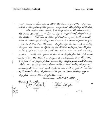
and raised or lowered, so that the lower edge of the cup or can, which is the guide of the yarn, may suit the filling of the bobbin. The cup or can rests & is hung upon a shoulder at the top of the spindle, and its cavity is sufficiently large to admit the bobbin. This can be lifted off & put on again with ease, it must be taken off to change the bobbin & to mount or piece the yarn when the bobbin is in the can. In finishing broken ends, or in finishing the yarn the bobbin is lifted by the thumb or finger from the pin or stud that connects it with the wheel, and the yarn is allowed to run while the yarn is put in a proper position to be mounted, then the thumb or finger is withdrawn from the bobbin & it falls to its proper place, reconnecting itself again with the wheel. When the spindles are placed close to each other, it may be necessary to surround each cup or can with a cylindrical, semi-cylindrical tube to prevent the yarns from interfering as they pass round their respective cans.
Providence Nov. 10, 1828.
Witnesses: M. A. Allen
J. M. V. Staples
John Thorp.
Page 4.
United States Patent
Patent No.: X5344
No Printed Specification Available
Substitute for Original
J. THORP.
Machine for Spinning and Twisting.
Patented Dec. 31, 1828.

Witnesses:
Inventor
Published accounts: journal notice
Notice in the monthly list of patents, with remarks
Journal of the Franklin Institute, new ser., vol. 3 (1829), p. 262 · View the page
22. For an improvement in Spinning, called a "Cap Spinner," being an improvement on the "Ring Groove Spinner;" John Thorp, Providence, Rhode Island, January 23.
Remarks. This will be noticed, together with several other improvements in spinning, recently patented by the same gentleman.
Published accounts: journal notice
Notice in the monthly list of patents, with remarks
Journal of the Franklin Institute, new ser., vol. 4 (1829), p. 67 · View the page
The plate is opened on the front by a narrow saw kerf, running obliquely through it from right to left, which allows a free passage of the yarn from the outside of the plate to the ring. -The spindles differ from others only in their being shorter above their upper bearing; they have a collar on them, on which the bobbin sets, and with which it is connected by two pins, or studs, extending upward, and entering two corresponding holes in the base of the bobbin. Either a common, or weaver's, bobbin may be used, and may be readily taken off and put on to the spindle. When constructed for a weaver's bobbin, the collar on which the bobbin rests has a spiral spring under it, and when the yarn breaks it can readily be pressed down, and joined, without taking the bobbin off. When on a common spinning bobbin the yarn breaks above the plate and ring, it must be taken off, in order to mend, or piece the yarn. The bobbin that is intended for the shuttle, has its shaft in two parts, being split nearly from point to head, which causes it to bind well when crowded on to the tongue of the shuttle. References to Fig. 4, Plate 1. A, is the bobbin-rail, B, the spindle rail, C, the foot rail, D, the spindle. } of a common spinning frame. E, the bobbin, connected with the collar, F, by pins, or studs. F, a collar which slides on the spindle, and is connected with it by the spiral spring, I, which being confined to the collar at the top, and to the spindle at the bottom, causes the collar and spindle to turn together. G, a box which forms the upper bearing of the spindle, D, and in which it turns. H, the circular plate, bolted to the rail, A, and which has in it a groove, in which the ring (represented by the white line,) is loosely THORP's Cap Spinner. placed, allowing the yarn to revolve around its surface. The opening of the plate is also seen. The shaft of the bobbin, E, is seen split for the purpose of spreading and tightening it. The yarn is shown as it comes down from the rollers of a common spinning frame. The detached figure, H, represents a ground view of the circular plate, and of the ring resting and playing upon J. Description of an Improvement in Spinning, denominated the "Cap Spinner," being an improvement on the Ring Groove Spinner. Patented by JOHN THORP, of Providence, Rhode Island, January 21st, 1829.
Remarks. THE circular plate described in the ring groove spinner, is in this improvement made deep, say about an inch, so as to form a tube, and is placed and confined like the plate in the former. There is in this apparatus, a part called the cap, which answers the purpose of a ring, in the ring groove spinner. This cap rests upon a rim which projects inwards about an eighth of an inch, on the lower edge of the tube; this cap is made in the form of a liquor tunnel, with its nose upwards; it encompasses the bobbin, which may be a common weaver's, or shuttle, bobbin, split in the manner and for the purpose described in the ring groove spinner. The loweredge of the cap, which acts on the yarn, is perfectly smooth and polished. When the bobbin is a common spinning, or throstle, bobbin, the cap is of one diameter throughout, forming a straight tube of the length of the bobbin, with a head at the top; which head is pierced through its centre, which steadies it on the spindle, or the tube may be considerably less in length, open at both ends, so as to allow the bobbin to pass up and down through it. A thin, round, flat piece of metal, larger in diameter than the largest diameter of the cap, with a tube long enough to steady it, is placed horizontally on the top of the bobbin, or spindle, so that it can be removed and replaced with ease. Small polished notches on the edge of this plate, assist the yarn in revolving round the cap. The plates and caps may be made of any suitable metal, and may be about one-sixteenth of an inch in thickness. Fig. 5th, plate 1, represents the cap spinner. A, A, A, are pieces of common step-rail, spindle-rail, and vibratingrail. B, a spindle of the common kind, excepting that it has no flyer. C, the whorl, confined to the spindle. D, a box, being the upper bearing of the spindle, and in which it turns. E, a common weaver's or shuttle bobbin, crowded on the spindle. F, the thin, tubular, circular plate. G, arms belonging to, and extending back from, the plate. H, an arm, or stud, extending upwards from the vibrating rail. THORP'S Improvement on the Can Spinner. I, A pin, or pivot, passing through the arms G, and stud H, forming a joint. K, the conical socket, called the cap. L, the thin, flat, notched, circular plate, fixed on the spindle. The yarn is represented as it comes down from the rollers of a common throstle, or spinning frame. The plate F, is about one-eighth of an inch thick, about an inch deep, and about one and three-eighths of an inch in diameter within. It is connected to the vibrating rail by a joint, as represented in the plate at G, H; the pin I, forming the pivot.
About this record
- Patentee
- the Name and Date index of patents
- Date
- the Name and Date index of patents, USPTO records
- Invention
- the Name and Date index of patents
- Listed in
- the Name and Date index of patents, USPTO records, the Journal of the Franklin Institute, Burke's List of Patents (1847)
- The Franklin Institute's journal spells the name differently.
- Burke's 1847 Patent Office list gives the same patent.