

Drawings and documents
Published accounts: specification
Specification printed in the Mirror of the Patent Office (1828) with its plate

American Journal of Improvements in the Useful Arts, and Mirror of the Patent Office, vol. 1 (1828), printed p. 323 · View the page
Transcription
Machine-read text of the specification as printed in the Mirror; not proofread. Check the page scan for figures, reference letters and spelling.
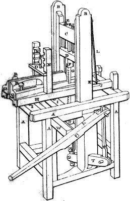
Pn th 4) A MACHINE FOR*MORTISING AND TENONING TIMBER, ahi a 4 By William Jackson and’J. J. Speed, Jr. of Caroline Township, Tompkins oun- Se one FORE: OL) ty, New-York—See plate XXIX. oe 4 0} eg WA voli Ggas! ont : cu rn want Construct a frame of convenient size, that is to say, about three we feet long, two feet four inches wide, and mye feet high, of suf- _ ficient, strength, with at least four pieces framed cross ways for a a.carriage to run on; two. posts to be framed, one on each side, Re set plum, standing on the inside of the frame; they should be of sufficient size and length for a gate, hereafter described, to play) Dy between, with three or four spursin each. Make a gate similar Mi toa common saw gate, with the addition of aslip rail, made fast to a o- the upper rail by two screws and nuts; this is for the purpose. of a?" we the saw and setting the chisel to any required depth. ye Make through the centre of the rails of the gate, a mortise about one and a half by three fourths of an inch, tenon into said rail a Yi piece one and,a half inches square; these pieces should, extend three inches in length on the, inside of the gate, and be of the size above mentioned: the. tenons extend through the slip rails into the upper, rail, and four inches through the lower, rail; these : are, to-liang the saw on; the lower one to be made fast by a pl 4 through the tenon at the lower edge, and the upper one by a fin at thas ppny edge of the slip rail. The saw is let into these pieges,.and fastened by.an iron pinat each end. ae ; : ‘On the outer edges of the gate, runa groove in the centre,for =. the purpose of shipping on the spurs in the posts above mentioned; the Jength.of the gate should be governed by the length of the : saw/used..... Make a carriage of sufficient strength of the length of the.frame; the width to be such as to slide through the saw ; gate, with four pieces or rails tenoned into the side pieces of the carriage; two other pieces.tenoned into the two middle rails about , one fourth of an inch apart, in the centre, so as to let the saw play through. The side pieces of the carriage must be grooved so as to slide.on.spurs set in the cross pieces of the top of the frame. A.rag iron fastened on the side of the carriage is moved by a a feeding hand, made fast to the lower end of a spring posts the sy spring post is secured at the upper end to.one of the side posts, — ee which. the saw gate plays between; the spring post is moved by a cog in one of the side pieces of the saw gate, which strikes ls the lower end of the spring post, and moves the carriage forward _— a every, time the gate moves up. Frame two pieces on each side : of the, carriage, and, cut grooves on the inner sides of each, so, nee thata piece may be slipped in cross ways of the carriage, with a _- serew through the centre, and be moved up and dewn so as fo correspond with the size of the timber to be mortised or tenoned, 3 ims The piece of timber to be mortised or tenoned, is, placed on the earriage and fastened down with the serew through the cross ; Ce SF -. Sele Wie a key es + deaae oe) Tee OPE SS Od ae ahs te aga ". AMERIoaN sOunmant.: 9 2 ee piece mentioned above. | For a set or gauge to ‘ole th timber to its proper place, take a piece of baa si e9s aneatiers e 34 corner, so.as to. leave the two. faced side about one inch and a , fourth thick: take off the edge of one of the faced sidessoas to” : form a wedge or key'on an angle of about'seven'degrees. Half an inch from the angled’ edge on the faced side, run’a groove from i oe Bs +, end to end; this set is moved on'two spurs; one spuron the end “piece and the other on the middle piece of the'Garriage, placed so that when the set slides endways on'the spurs, it will always be on a parallel line with the side of the saw; by moving this piece ss end ways, it will regulate the timber'so as to bring the gauge if stroke on the timber to its proper place. The'set'is made fast ee by a screw through a slip mortise, cut on the’same angle withthe aaa groove. On the other side of the timber a similar set or gauge is placed, and moved in the same way.’ A short piece or pitmar is attached to the tenon of the piece that passes through the lower rail of the saw gate. The lower end of the pitman is attached 7 to the end of a balance that turns on its centre at the side post of the frame: On the other end of the balance, and at an’ equal‘dis- Ee tance from the centre, is attached another piece or pitman, of about the ‘same length: ‘to the upper end of the last’ mentioned Pa piece, is attached a lever, to be hung’ on a bearer made fast to the . frame for that. purpose. For sawing, the lever isso hung’ that the bb short end,or end attached to the pitman, may be half the length ofthe balance before described, and the long end‘of’ any convenient length. For mortising, the motion required is much less than a “4 _ that for sawing, and the’short end of th lever should not be more Me than on ’ fourth of the ‘length of the’ balance. “ When’ used ‘for "ss mortising, the saw must be taken out, together withthe piece through the upper end of the saw gate, and a piece similar to th Se ohe taken out, with a socket on the lower end, is to’ be’ put in; when in, the chisel is to be put into the socket and made’fast by , a screw. S ATQONATE a The chisels to be used may be the common mortisifg chisel; the grooved chisel, or the common mortising chisel ‘with a'steel spring on the back, having a beard on the lower end of the spring : next to the chisel, to lift out the core or chips. ‘Phe spring chisel as above described, we consider preferable to any other, and claim it as our own invention. To enmmenc a mortise, bore a oi hole at the end, the depth of the mortise. This machine’is put in motion, and all the operations of mortising, &c? daca ed by the operator applying his force to the’ lever before nam- We do not, however, confine ourselves to ‘the lever, as "a Moving power; the operations of this machine may ‘be performed in various ways, by wheel, crank, treadles or spring’ pole. Neither do'we confine ourselves to tenoning, for we consider the mara a * ee > rg. Fe a gee Sie 4 ey Lt i 2 s Pets a aid i: PAC ise r ety | . gon Brew, coy) Sacra iis’ AM Re Jia a ", ; ie ‘See aihes in epee th qe. Rs Ms a ‘[sbilati Bites, ae aigaaney: jaa Laka Brive R k o4,* * a pets acta! ag NRL 2A hate Se aaa iat) Ge ee a) 2 a:
ie ultaae 3! 5c , ; winged. yh oir Wigley 7 yr Sires sy ou Se Hi? Mises mit toga fat Mie eee me AIC te spines ; PLEN AN chine useful for any'kihd of straight sawing. The carriage can ‘a ‘be sshyed by. handape mer) or, otherwise. gy ei HL saw or chisel may also be hung in various ways; a par- Be Er ar ah : Fi m eg ticular description of which is deemed unnecessary What we , claim as our invention, is the particular construction, as described a by’us; of the s or'gauge, for confining and regulating the tim-8 + A Dis bers “Also the slip rail ‘in the gate for regulating the depth of the’ oi Hr chisel, and straining the saw; together with the spring chisel ~ Ge before mentioned. . > ial P PRSTRQORN! a TR Oqgo mas We also claim, as a new application of parts heretofore known and used, the saw gate, carriage, balauce and leve sas betovredes= ofbedg itt. RRS egos A (ob: OSE alae) be me Pate of the patent, 20th September, 1826. 0 ae Nate. on etanienw oki ; see i. ee ry Bas paeet SE 1) nea ‘ a kobe Gt eit.
‘i 5 TD Ad RETO gS 3 than PEE 5, ie A A? <6: , 19k at wha RTC a TS LER Ye, ex op es a SS. eevee PRE OE =. a Sg Seger Bate Saba ae “eas: aie a ote eal : oem ae fad mS IO BHD. OS ARFERENCES-PEATE XXIx. | |S Ree. OT oe wa Henge! wae ‘ WP att sighs ih By Eavk Sg ae je ‘ ie. frame to support the carriage. ey nee 1 a opty ae Res. B_ The two.upright posts for the gate to playin. . at irae : a “ bat Ss ip) age e saw gate. ; Roe tens ee eS as ee gee og GOs | - Sh 0 Sree me K, D The slip rail. “3 + yo ai heute “ONS Peto screws and nuts for regulating the chiseland straining the We RSS aaa, sip iPBes and lower pieces for hanging the saw. ~ os ee 3 2 1 a i /& 4 T je Ve vend’ ahaa oe Sep HL The carriage, hi te SN oe A “The Spurs on the top of the frame for the carriage to move on, _ a as ‘Y) The bag. Son. a! Matt Son hs “K The feeding hand. ~ ce s2 be peta eS: Le The spring post, oe hie. Oe The cog in the side piece of the saw gate, to strike the spring” post, ia. Ms “and move forward the feeding hand. , Sy ge SAS ee cee “Sh “ The grooved upright pieces on the carriage. = ; i ea : ae Sy re 'The'slip cross piece. he ae ee s REIS P) The screw to confine the timber to be mortised. Mao 3 vas i BS Aa @ The two grooved pieces, of a wedge form, fora setorgauge, = ee RR The two screws passing through a slip mortise, for screwing the guug 2 N __ to the carriage. “ Bees elie ee oe 2,80 - The pitman. da > aa ope ath em as mi “Po \ The balance. , iis: eae ae FS a tk *G 5 The pitman connecting the lever and balance. Soa bode. ae Ss God The lever. *. ESE ee at a W = The lever-bearer, ges Migbouds peie an ont gpk oem hae 7 3 ih Shown: : c | : ic DOE | <a mit ete’ Searaoett es Fe ; wre” ee EP T Wh Cpe ees b * - a rn eR IMPROVEMENT IN THE GRIST MILL, 6) 4) sy.
Published accounts: journal notice
Notice in the monthly list of patents, with remarks
Journal of the Franklin Institute, vol. 6 (1828), p. 395 · View the page
8. A machine for Mortising and Tenoning Timber; William Jackson and J. J. Speed, jr. Speedsville, Tompkins county, New York, October 10.
Remarks. The general construction of this machine is that of a common saw mill in miniature; there being a frame with a carriage on it, upon which the piece to be mortised, or tenoned, is to be secured. There is an ingenious, but simple contrivance, for shifting the pieces laterally, so as to adjust them, by bringing the gauge marks to the saw, or chisel. A saw is strained in the frame, when tenons are to be cut; and this, for mortising, is to be replaced by a chisel. There is a slip rail attached to the saw frame, for straining the saw, or for adjusting the chisel so as to enter the proper depth. A feeding arm causes the carriage to advance, by working on a straight rack. The ordinary mode of working the frame, is by a lever, in the manner of the common pump handle. "The chisels to be used, may be the common mortising chisel, the grooved chisel, or the common mortising chisel, with a steel spring on the back, having a beard on the lower end of the spring next to the chisel, to lift out the core or chips." "What we claim as our invention, is the particular construction, as described by us, of the set or gauge for confining and regulating the timber. Also the slip rail in the gate, regulating the depth of the chisel, and straining the saw, together with the spring chisel before mentioned." "We also claim as a new application of parts heretofore known and used, the saw gate, balance, and lever, as before described."
DATAMP: illustration
Illustrations from DATAMP
DATAMP (Directory of American Tool and Machinery Patents), via the Internet Archive · Archived DATAMP page
About this record
- Patentee
- DATAMP
- Date
- DATAMP
- Invention
- DATAMP
- Listed in
- the Name and Date index of patents, DATAMP, Jim Shaw's X-patent list, the Journal of the Franklin Institute, the Mirror of the Patent Office (1828), Burke's List of Patents (1847)
- The sources give different dates; the date shown is the one most of them agree on.
- A drawing was printed in the Mirror of the Patent Office (1828).
- The Franklin Institute's journal gives a different date.
- The specification was printed in the Mirror of the Patent Office (1828).
- in_burke
- burke_date_differs