

Drawings and documents
National Archives restored drawings: drawing
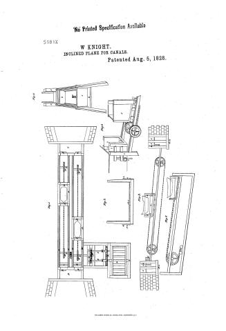
William Knight's Patent Drawing for an Improvement in the Mode of Raising and Lowering Canal Boats on Inclined Planes

National Archives, Restored Patent Drawings (Record Group 241) · Full-size scan at the National Archives · Catalog record
Text on the drawing
Words on the drawing as machine-read by the National Archives; not checked. Useful mainly for searching.
ILIC ENGINEERING. / inals / $4450 / WILLIAM KNIGHT'S / 5181. / Impf in the urode of raising & lowering Canal boats on inclined planes. / Fig. 1. / Patented: 5* May; 1828. / Fig: 5. / No / Fig:4. / Fig:3. / 40 / 14 / 16.2 / N° / big 2 / Ti / Pdit / (.) / 16.3 / 16.4
USPTO scan
The patent as scanned by the USPTO
-
 Page 1
-
 Page 2


U.S. Patent and Trademark Office · Google Patents
Published accounts: specification
Specification printed in the Mirror of the Patent Office (1828) with its plate


American Journal of Improvements in the Useful Arts, and Mirror of the Patent Office, vol. 1 (1828), printed p. 305 · View the page
Transcription
Machine-read text of the specification as printed in the Mirror; not proofread. Check the page scan for figures, reference letters and spelling.
on | METHOD OP RAISING AND LOWERING BOATS. By William Knight, of Morristown, Morris county, N. Jersey—See plate XXVIII" ei i: Pig ai Specification My improvements will be ‘better understood, by contrasting them with the plan now attempted by the Morris Canal Company, in this vicinity, which is to draw the loaded boat over the plane dry, in a sort of cradle, or frame, attached se to four large wheels, moved by a vertical water wheel at the head of the plane; the whole apparatus resembling a large , ea wagon moving up the plane, by a chain attached to the water soe wheel and the cradle frame with the loaded boat, moving under the wheels, and the whole weight resting on four points of the lane.
The first objection to this plan is, that the loaded boat, not 5 resting on water, but supported only at certain points in the cradle frame, must incur much hazard of being made leaky, by overstraining the joints. By my plan, the boat is carried over the plane in a car filled with water, and is equally supported at all points, as when in the canal.
Another objection is, that the power, which necessarily is great to draw up a loaded boat, requires a much heavier chain seam and stronger machinery throughout, involving a heavier expense, Pcs with more risk of breaking; the wheels resting, with the whole weight, upon a few points, the plane will be liable to be injured, With my improvement, the ascending and descending cars, being at all times balanced, as well when but one boat is passing as when two are moving, no more power is required to move them than is necessary to overcome friction, and the chain and other connecting parts of the machinery are comparatively lighter and less expensive. The car, also, moving upon forty wheels or more, resting upon as many points, will do less injury to the lane.
A third objection is, that the boat, with its appendages, is to : be carried over and above the water surface of the canal, and | 4 again descends by another plane into it; and upon my plan, it yises to the water level in the canal and no higher, and imme- Bately ursues its journey with much less detention than is oc- . 4 bh pomp by locks or any other mode known to me. My plan presents simply the idea of a boat moving up or down the plane, resting in her car, which is a moving floom, carrying the boat from one section of the canal to another. This car, or moving floom, is constructed with permanent sides and Boge moveable ends, so as to answer the purpose of gates, dropping : perpendicularly into boxes placed to receive them, admitting : the boat to pass from the canal into the car at one end, and from : ‘A the car into the canal at the other rd. The structure of the a Ciao ee Oe | ee ts ee 5 Sh outg ae it, 2 a ae Cats ie aes. us eae a AMBRICAN JOURNAL. % ea eanal at the termination of each section, is like that of a floom, . id with a plank floor, supported by timbers and a wing wall, and made accessible under the floor of the floom, to rebuild or repair the water box into which the drop gate falls. The breast ofthe saad floom must be as long as the plane is wide, viz. the width oftwo boat paths; and the width of the canal, at each termination, must os be sufficient to admit two boats to pass together, as the plane performs the office of a double lock. The plane, at each end, terminates with, and is joined to, the breast of the canal floom, Se or as I have termed it, guard lock. In the breast are two drop gates, one to each boat path, of the width of the boat, with a water box under each to receive the gate, similar to'the drop gates and water boxes of the car, admitting the boat intothe canal from the car and into the car, from the canal. ss When the car has reached that section of the canal towards which she is travelling, and presses upon the breast of the canal floom, or guard lock, as I propose to call it hereafter, itforces a slide into the place prepared for it in the canal, to which slide is attached a sort of leather valve, fastened at its other end to, the guard lock, and this prevents loss of water between *, es the car and guard lock; making one continuous floom, upon the Ber same water level, and upon which the boat moves into the 4 is eanal. z ; re a The inclined plane may be constructed of stone or wood,or both, in the usual manner, and ni por of sustaining the weight of a loaded boat and its car, which I-estimate may be about 80 Pi to 100 tons. The length of the plane must be proportionate to the elevation or height to be overcome, and its width sufficient to allow two boat paths. The perpendicular rise of the plane which I would prefer, should be about one foot in every ten feet of the plane; should it be greater, the strength of the chain and driving shaft must ‘be proportionate. The elevation may be 50 or 500 feet, provided the plane be of proportionate length; and wherever, upon the lineof the canal, there is an elevation of from is 20 to 500 feet, the difference of expense between locks and an fnelined plane will be as much as 33} per cent. in favor of the aa latter. A “The machinery may be propelled by water, steam, or horse power; as the power required will be but small, I should prefer ae water in all cases where there is a tolerable supply for the canal, and my drawings are designed for water power. sey By. “The shafts, wheels and pinions which are used, are constructa ed in the usual manner, and any mechanic acquainted with mill machinery and floom building, will be able to construet the whole without other instructions than such as will be given in the explainations of the figures and views in the drawings, with those immediately connected with my improvement afd invention. The oF v4 ay sp eal 2 a hee etre he ee ee ere ge a SY hia: iw *. wes, At: le . :
aR : Fo, bees endless chains revolving upon vertical wheels, will be made to ares admit a cog into each jiuk, to prevent them from sliding, and to move the whole with uniformity and regularity. : EXPLANATION OF THE ACCOMPANYING DRAWINGS: * a Camere f Fig. I, Sal Is a ground view of an inclined plane, with the cars and boats moved by two endless chains, working on vertical wheeis, ee or pulleys, with the water wheel and machinery that puts them rest in motion, with a section of the canal, its upper and lower level, 1g ‘This figure will be understood by laying the sheet flat and looking down on the top of it, A A, the bottom of the two cars and _ boats, supposed to be on their passage, one up and the other down; B the upper level, C the lower level of the canal; DE are the openings, or water boxes, within the guard locks, be or flooms, of the upper and lower levels of the canal, into which the drop gates fall, as the boats pass into and out of the canal. These drop gates are raised and lowered by a rack and pinion, gp any other convenient mode; H I are two openings, or water . boxes, outside of the floom and under the plane, to receive the _ ; two upper gates in the cars and to let boats pass in and out of cas the cars. The boxes HI are hung on levers that move them up to the bottom of the cars, when they arrive at the upper con and shut, water tight, under the openings J K in the end of the ears, which openings are to receive the drop gates of the cars; are the openings, or boxes, in the other ends of the ears, to receive the drop gates, in the same manner as the others. The water boxes in the lower ends of the cars, are attached to the cars and travel with them, whilst those which receive the drop gates of the car at its upper end are stationed at the upper end of the plane. If these were attached to the car, they would interfere with the vertical chain wheel; at the lower end of the car, there is no such interference. N N NN, four cast iron vertical ~ : wheels, or pulleys, around which pass two endless chains,one = made fast to each car. OOOO, the iron shafts of the vertical wheels. The shafts of these vertical wheels are placed across _ as the plane, at the distance of nearly half the length of the car, he measuring from the guard lock. The two lower shafts and cer wheels are for the purpose of directing the endless chains 4 and keeping them in a proper degree of tension, and as the chain must pass under the surface of the plane, the plane must beso constructed as to leave a space for its passage. Pisapairof spur wheels connecting the movement of the cars, and carrying oumeuP. and the other down at the same time. Q isthe water wheel; R, two spur wheels to give motion to the iron shafts oy 8, which are connected by coupling boxes to the main shaft of a Rea ae Se oe f ‘ Ay = ; y age n r i pe Sn Ny sd the water wheel at a; Aa, then, is another coupling box, both allowing liberty to these shafts S S to move into and out of gear. . "fis a spur wheel at the end of the iron shaft O, that gives mofeo tion to the chain wheels. U U are.two pinions working into the Lett wheel T elternately, to reverse the motion of the cars, as the pre drawing shows. V is a sliding head block, worked by a lever, fae Ns to move the pinions U U, one out and the other into gear, or both out, to stop the cars when the water wheel is in motion. W ate iron bars spiked or bolted on the way-timbers vesting on the walls of the inclined plane. The friction rollers, or wheels, attached to the under side of the cars, move on the iron bars, with a flange to guide the cars in a straight line. Ee Is an elevation or side view of one of the cars and boats on its _ passage to the upper level of the canal. A the car and boat; a _ NN two chain wheels, or pulleys; H is a water box that is raised by a lever under the opening H in the ground view, to receive the gate I. No. 4 is a gate sliding horizontally under the LX f drop gate J in the car, to stop the water when the car is on its Ps, passage. L a drop gate at the lower end of the car, to drop in Be the water box X, to admit the boat to pass from the car into the iy lower level. D is adrop gate in the upper guard lock or floom, falling into the box below it, when the boats pass in and out. Ga similar gate at the lower lock or floom. 3 and 4 a part of the timber and stone work at the ends of the plane. 5555 show the water at both ends of the canal floom. 6 the friction rollers, or wheels on which the cars move. aa ; Fig. HI, Represents an end view of the frame of the cars, and shows hew to frame them without cap timbers across the top. la serew bolt passing through the frame just above the bottom plank. 22 a bar of iron on each outside of the timber. 4444 screw bolts through the upper ends of the bars 22, to make Se them fast to the post and resist the pressure of the water. The car is to be made large enough to receive the largest boats on the canal, and as light as any floom forebay, or trunk, a for a factory or mill. ‘Its frame consists of sills and upright _ posts; the planks are put on inside the timbers; and the ends are formed by what I have called drop gates, described heretofore. The sills are framed lengthwise, having friction rollers fi under them, at proper distances, to support the weight and move easily on the plane, upon iron bars made fast to the upper timbers ie _ of the et As the sills of the car, when in motion, must be mettle with the plane, the upright parts of the car must be Fae ramed so as to stand perpendicularly when moving, and th inoO n yale en es eT Palio Lees Sy om Sys ee as Cee ae ee eee: eres et is el ge Bi 4 ies Us 0 Se ee 4 ire es ; Bie ie ot eee ake Bi at he ts 5 OE eas ‘ehination of the, ogi inti always be regulated by the elevation are the plane. _The ends of the cars are now to be reversed, 4 therefore, the end next to the upper section of the canal willhave its posts so much shorter than those at the opposite end, as that a : Tine from the top of the short to the top of the long posts shall _ . be parallel with the horizon, when the car is moving on the ene as in figure Il, where the water surface represents the as orizontal line. The space in which the letter A of this figure stands is open, and the water bottom represented by the next os line above, and the water scen, as it were, through the side of. the bans of the boat. ’ shyt fee xint :
Fig IV, a hs Shows a perspective view of the guard lock and front end of is fea: the car, with the slide and leather valve ready to receive the ear. 1 1 the front posts of the guard lock, or breast of the floom. " 1) the frame to which the leather valve is made fast by small. serews, or flat headed nails, to the posts of the guard lock upon =, the sides and at the bottom, and again to the upright of the frame, : at its sides and bottom. 333 show the two sides and bottom Fs of the leather valve. 4 rack pinion and weight to carry out oS the slide and valve from the-guard lock to receive the car; this Teather must not be more than four or five inches in length, from. the posts of the guard lock. As the car approaches and meets this shding valve, its side pieces slide back through the upright 1, ~_ crowding the whole machine close to the guard lock, and wind- Ing up the weight on the pinion shaft at 4. The drop gates are now ready to fall and admit the passage of the boat into or out of the car. Where the saving of water is not a great object, this * : whole apparatus of the sliding valve may be dispensed with, and ne the car ‘es moved in close contact with the guard lock, in which a ease probably not more than sixty gallons of water would be lost by admitting a boat into the canal. The expense, however, Of the slide will be but a trifle, and will prevent the water from gushing so as to incommode the hands. 5 shows part of the ear. 6 shows a.stop, which, for safety, | would attach to each: Pes side of the car at its centre, to prevent its running down the “a he plane, if a chain should break. It is.a moveable timber, made a fast to the car frame, with a foot, as at 6, moving an inch or less above the rail of the plane, and which, by a screw and lever. _ a above, being forced down upon:the rail, at once fastens the car in its place. The captain of the car should have his station-post at its top, whence he can oversee every movement, and if neces- SEES sary, by asingle turn of the lever force down the stop upon the ail, when the car first comes in contact with the slide. I pro- S. pose to have it shut the gate which admits the water upon the ~ a wheel, as is done by the carriage of a saw mill 8. The spur | 3 SER * ay ok ‘ = ake oh See ae :
yale oe ae aN Ae et Maree te ey ee ee a f ba ah yi on Bi Jamie eae Aaa Gre bei whe AMBRICAN JOURNAL. ee ie wheel, which drives the shaft of the chainwheel 7, raiseda little above its true position, the better to distinguish it from. Fig. V, is Shows a perspective view of the rail way and @ partof the car, drawn for the purpose of showing the small sliding hofe rizontal gate at the upper end of the car, to render the car water tight when the opening is made in its bottom, through which its drop gate falls into its water box, stationed upon the rail way. The person viewing this figure is supposed to stand _ near the hinder end of the car, and ooking over its front end, he Pie sees through the lower space, the vertical chain wheel, 6, and the open space which is under the plane and the floom, the upbi per space looking into the canal. 1 is the drop gate, or upper By endof the car, ‘shutting down perpendicularly, and water tight, upon the small sliding horizontal gate, marked 2, which is level with the car bottom: This drop gate stands perpendicularly. upon the horizontal gate, and both are represented by a common door when shut, arid its lower edge resting upon its sill. 3 the staa tionary water box, to receive the drop gate. 1, when the car is aed carried up to the guard lock at 55. 4 4 two small levers, conie nected at their upper ends to the water box 3 and fastened near their centre to the inside of the rail way. The car approachbee ing the guard lock, passes over the lower ends of the levers and _ brings up the water box in close contact with the opening in the bottom, into which the drop gate falls, as soon as the horizontal gate is thrown back by the rack and pinion, to be moved by had. 6 part of the vertical chain wheel.
he jen Fig VI, “f Shows a side view of a car, with a flat chain and cogs on the hes wheel working into the links, to prevent it from sliding. It also ee shows a truck carrying the end of the chain down its rail way under the plane, as the boat ascends, in cases where the endless ag chain is not used. I should, however, give preference to the endless chain. : sis ga Having described the machinery and apparatus separately and Be connectedly with the mode of forming and combining the whole, Bae I propose, im order to render the whole process more clear and intelligible, to conduct a boat from the lower to the upper section of the canal. For this purpose, we will suppose the boat a -. arrived at the termination of the lower section, and stationed in the water, represented at 5 5, in the lower section, fig. H. The ead ear is then moved close to the breast of the floom, or guard lock, forcing hack into the floom the slide with the leather valve ata ~~ tached at one end to it, and the other end of the leather valve to Bi _ the end of the guard Jock, which prevents the waste of water at” eo 8 ‘i im Pere 7 ee ee oe ate ee macs ks ape euiedl Shige ee ie, Raw * ~, AoE. , ’ Se Be ii has a ‘ ++ y aks 2 : be fe Siaeets * * + ; a ‘pet AstntCA JOURNALS 6 Sir My rb p< sting Ser landng guard lock. The drop gates G a of the floom and L of. eee, are now dropped, by means of a aa rack and pinion, each into its water box beneath, and thus the P car becomes a continuous canal, the water flowing into it tothe 4 same depth and ‘height as inthe canal. These drop gates, now a removed and affordmg a passage for the boat, it is pushed forward into the car and immediately the drop gates are raised from the water boxes, to prevent the water escaping from the ; eanal-and from the car when they separate. If the water wheel -, has been kept moving whilst the car was receiving the boat, — il both of the shafts S, fig. I, remain out of gear, whilst the car rests. Being now ready to move, the moveable head block,.V, ie fig. 1, is moved to ‘throw one shaft into gear, and immediately Wl the car moves upwardon the plane to the upper section. As if starts from ‘the ‘lower section, and brings the other car down to : 4 the lower, the weight connected. with the slide forces it out the 4 width of the leather valve; where it remains in readiness to re- ‘oa ceive the car when it returns. At the upper section a similar a slide and valve is moved by the same means and for the same 4 purpose as below, and receives the car, which is now in close : contact with the raw guard lock or floom. |The stationary “y water box H, fig. 1, being raised by the small lever attached, is 2 brought close to the opening in the bottom of the car,andimmediately under the drop gate J. The horizontal sliding gate 4 is ee moved ‘by rack and pinion into its recess at the bottom ofthe car, and admits the drop gate J to fall into water box H, atthe same time drop gate D falls into its box underneath, and thus theear becomes a continuous canal with the upper section, with the aa water at the same level and of the same depth as represented at of the upper section, and the boat is now moved through the ao ‘spaces of the drop gates from the car through the guard lock oa into the canal, and proceeds on her'voyage. ‘The same process . ae reversed brings the car and boat from the upper to the lower =.) section; and when two boats are ready and waiting, one toascend and the other to descend, (which will rarely occur at the same monient,) they can both move at once, in opposite directions, as aS represented at fig. 1. But when one boat only is to pass, the op- 3 is posite car travels in the other direction, freighted with water 4 only, as counter balance to the other car and boat. gran? ‘Having described the process of conducting a boat fromone — ; a section of the canal over the plane to another section, I pr ae oa now to trace the moving power from the main shaft of the wer a wheel to the other machinery, and show the effect upon each ee part. -When-the main shaft O, fig. I, is put in motion by ay be cee 3 steam, or horse power, the spur wheel on said shaft will put t . SS ‘wheel and:shaft which gear into it, at R, in motion also, and in Opposite directions. These wheels, coupled by the boxes aa a aie a ae 49 + ifthe’ il with the shafts S 5, impart the same motion to them. . These coupling boxes, a a, being a sort of point, admit a slight motion at the joint, sufficient to change the direction of the shafts S S from a straight line with the main shaft. The other.ends of these A two shafts $'S at V, revolve upon a sliding head. block, which can be move at pleasure by the hand, with a small lever attachie ed to the block. Their ends are placed on the block at such distance from each other, as that when the centre of ,the block is mY perpendicular to the centre of the shaft O, which carries the wheel T, the two shafts 5S will revolve without either one gearing with the wheel T. By moving the head block so_as to ie throw the shafts S V into gear with the wheel T, it will throw a 2 the shaft S U further out of gear. By this block, it is evident, se that you may at pleasure throw ezther one of the shafts SSimto gear and the other out. or throw both out, whilst you cannot put , ge both into gear at the same time. Should they by accident, or by design, be displaced so that both should gear with T as. they Move in opposite directions, one or both must be. broken or 2% thrown off. Suppose these* small wheels both out of gear, and a _ the main shaft moving, the car will be at rest. Now by the lever move the head block V, so as to put the shaft S Vin gear, you put the chain shaft O T in motion, carrying the chain, wheel upon it.. The chain passing over the two wheels NN nearthe . aed two ends of the plane, and made fast to the car, will move the ete car and boat to the upper section of the canal. . The small spur wheel P gearing with the small spur wheel near it, puts in motion in an opposite direction, the upper chain wheel of the oe other boat path, and the chain by its -connection with the “ar, carries it and the boat to the lower section of the canal. a9 When it is desired to bring this last car from the lower to the upper section, and the other car from the upper’to the lower section, you move the sliding head block V so as to throw the shaft S U T into gear with the wheel T, and c nsequently throw shaft S V, which had been performing the labor, out of gear. __ ee This movement of the head block reverses the movement of the : chain shaft T O, and with it is reversed the movement of the — “ay chain wheels and the cars. By the position of the shaftsSS,as om represented in fig. I, of the drawing, it is obvious, that by shift- si ing the head block V, as mentioned, so as to place shaft S V in ma? gear, it will remain in a right line with the main shaft 0, and when the block is shifted to throw the other shafts S U T into : gear, it will remain parallel. with the main shaft O, and thus they . Pee will be less liable to be injured ‘or overstrained when laboring, ews than if they gave motion to the chain wheels by revolying not in a line or parallel with shaft O.
if - | In this method of carrying canal boats from one section of a ‘canal to another, upon an inclined plane, I wish to be mderstond J ; if as hot claiming the’ plane, or wheel, or chain, or car, as my in- ; vention. What I do claim as my own particular invention, and wish to secure to myself and my heirs the benefits of, by patent, : are, Ist. The peculiar construction of the car or moving floom, with the ends answering the purpose of gates dropping into boxes water tight. 2d. The peculiar structure of the canal at its junction with the plane, answering the purpose of a permanent floom, with similar drop gates and boxes. 3d. The slide and leather valve, to make the junction of the car and guard lock water tight. 4th. The moveable head block, shifted occasionally, to throw the moving shafts and pinions into gear and out of gear, to reverse the motion of the car in such a manner as that the laboring . a shaft is always kept in a straight line. 5th. Although I do not claim as my invention any of the mechanical powers which I use, yet I consider myself entitled to claim as an improvement, and do claim as such, this particular combination and arrangement of : these mechanical powers with endless chains, moving over ver- eg tical wheels, and delivering one car at the same time at each end of the plane, by moving in opposite directions. , And I claim the, benefit of my invention and improvements described above, to such other purposes as by further experience they may be found . useful, being well satisfied they may be advantageously applied, to raising ships and steam-boats out of the water to repair’ their bottoms, and may be stationed upon rail roads to draw trains’ of we loaded wagons over hills and other purposes. Date of the Patent, August 5th, 1828.
[References to the plate, as printed:]
a IMPROVED BEE HIVE. :
Published accounts: journal notice
Notice in the monthly list of patents, with remarks
Journal of the Franklin Institute, vol. 6 (1828), p. 252 · View the page
4. An improvement in the mode of Raising and lowering 1 canal boats, on inclined planes; William Knight, Morristown, New Jersey, August 5.
Remarks. The importance of the subject of inclined planes is such, as to demand our particular attention to every thing which presents itself in the form of an improvement. If, upon a more careful examination of Mr. Knight's specification, we think that his plan can be understood without drawings, we will make an abstract of it in our next number; otherwise it shall hereafter be illustrated by engravings. The main feature of his plan is, to raise and lower the boats, floating in a car, supported upon numerous wheels. The car to have water-tight gates at each end, one pair of which is to be opened to allow the boat to float in, or out, at the lower level; the other pair to be opened to allow the boat to pass in or out, at the upper level; there being leather valves, &c. used to make the car fit water-tight against the entrance, or mouth of the canal, at the upper level, previously to opening the respective gates which close the end of the car, and the entrance of the canal.
About this record
- Patentee
- DATAMP
- Date
- the Name and Date index of patents, DATAMP, USPTO records
- Invention
- DATAMP
- Listed in
- the Name and Date index of patents, DATAMP, USPTO records, Jim Shaw's X-patent list, the Journal of the Franklin Institute, the Mirror of the Patent Office (1828), Burke's List of Patents (1847)
- A drawing was printed in the Mirror of the Patent Office (1828).
- The specification was printed in the Mirror of the Patent Office (1828).
- The Mirror of the Patent Office's supplementary list gives the same patent.
- in_burke
- burke_date_differs