

Drawings and documents
National Archives restored drawings: drawing
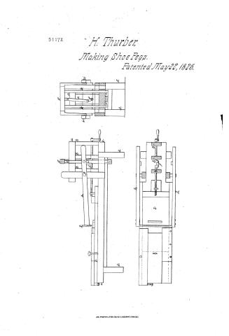
H. Thurber's Patent Drawing for a Cutting Press

National Archives, Restored Patent Drawings (Record Group 241) · Full-size scan at the National Archives · Catalog record
Text on the drawing
Words on the drawing as machine-read by the National Archives; not checked. Useful mainly for searching.
144. WOOD WORKING MACHINES. / Slicers - Polity f Oscil, / Polity page 211 / Slicers, Rotary & Oscillating. / classi, 1TION / III TEURBER / 5117-4 / DIVISION / culling Pegs / Palented 22.May 1828. / Company / bonrd / n Pasts / Azan / Cronk / Verlical / cullerframe / Steel culler / Curriage / Patent office May 31' 1841 / Made under the direction of the of Talents / Strichland Del / in componuty with acto 3 d March 1837 / commitroner of Patents
USPTO scan
The patent as scanned by the USPTO
-
 Page 1
-
 Page 2


U.S. Patent and Trademark Office · Google Patents
Published accounts: specification
Specification printed in the Mirror of the Patent Office (1828) with its plate

American Journal of Improvements in the Useful Arts, and Mirror of the Patent Office, vol. 1 (1828), printed p. 167 · View the page
Transcription
Machine-read text of the specification as printed in the Mirror; not proofread. Check the page scan for figures, reference letters and spelling.
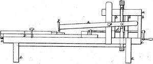
MACHINE FOR CUTTING PEGS. ee a By Hezekiah Thurber, of Steuben county, New York. i : aM et See plate XVII. figs.1to3. oe Specification —This machine is constructed in: the following ik manner:—A frame is made of suitable materials, three feet long A and eight inches wide, supported by four posts, six inches high, ae on which is placed a board two inches thick, three feet and six oe inches long, and breadth as follows, viz. two feet and a half is is eight inches, and. the remaining foot is six inches wide, in the: iS end six inches wide; ‘and in the centre of this board are inserted ae three uprights, seven inches high, three inches broad andone inch thick, placed three inches apart, and forming a spaceof nine inches. The first upright is placed at the end of the board—on the top of three uprights is mortised a top-piece, a the same breadth and thickness of the bottom board, and one > Sag foot long. In the centre of the top-piece, between the second at ‘and third uprights, a mortise is cut sufficiently large to admit an a arm to pass through, which is attached to a crank—which crank a is an inch and a half long, giving a sweep of three inches, and og passing through the centre of the three uprights, is placed be- ae tween the second and third uprights, two inches from the bot- aad tom board. This crank gives.motion to the vertical cutter frame; and to the end of said crank a screw is attached, which a gives motion to the carriage, on which is placed the wood in- eh tended. ‘to be cut into pegs. The above mentioned vertical See frame should be thirteen inches long and five inches wide, so as Bae, to admit of its being let into the bottom board and top-piece, ere that it may work similar to a saw gate. The horizontal cutter ae frame is constructed of two pieces of timber, two feet: long, one aS inch thick, and one inch and a half broad, and made sufficiently a broad to admit of being affixed to, and on the outside, of the ver- Po tical frame, by two pieces of iron, six inches long, one end of a each screwed to the vertical frame near the top, on each side of a. the same, the other end rivetted to the horizontal frame; two pieces of timber of suitable dimensions are screwed on the out- a side of the bottom board and top piece, three inches from the vertical frame, standing perpendicularly. "The horizontal frame works on an axis passing through it three inches and a half from Re the rivet that attaches the iron to the same, and through these timbers four inches from the bottom board. On the outer end ae of the horizontal frame, is affixed with bolts and screws, a steel RS: eutter, ten inches Jong, two inches anda half broad, and one- ae fourth of an inch thick, running to an edge from the inside, the aS outside being perfectly straight; each end of this knife, for one = a PL eS eee Wee Pe Oey ie i ae BF af a ee a ' inch, is made square, so as to fall on two plates of iron, and i . thereby prevent the knife from cutting the carriage after passing through the peg timber on each edge of the bottom board; a ng piece of timber, two feet six inches long, three inches wide, and afi one inch thick, is nailed for the carriage to work in the same, ‘a being moved by a screw attached to the crank. The carriage is eighteen inches long, and eight ‘inches broad, and one inch “i thick. On the end next the crank, a cross piece, eight inches will Jong, two inches broad, and one inch thick, is screwed down ia firmly. On the inside of the cross piece, in the centre of the carriage, is fixed a piece of timber, five inches long, three inches a broad, and one inch thick, one end. fastened under the cross a piece, and the other end is fastened by a button; on the above he mentioned piece of timber is fastened a clamp, in which the Bs: screw works, attached to the crank; the clamp is fastened by a a spring on the other end, and in the centre of the carriage a piece is of timber is fixed across, four inches long and half an inch ge square, to prevent the wood intended to be cut into pegs from ae slipping back. A piece of timber, eight inches long and one. a inch thick, is nailed to the top of the bottom board, at the end ia of the same; a piece-of timber, ten inches long, ,three inches ae wide, and one inch thick, is screwed on the top of one of the outside timbers, so that one end comes close up to the cutter; ea on the other outside timber; another piece seventeen inches long, three inches wide, and one inch thick, is placed with one end iam close up to the knife, with a screw passing through it, nine ae inches from the cutter, and forming a pivot for said piece to a move on; on the extreme end of the bottom board, a nut and Ms screw is affixed which operates on the piece of timber, moving on its pivot, and causes it to press sideways on the peg timber, a as a vice, which holds the wood or timber intended to be cut a into pegs perfectly firm, and between the pieces above described; a | another piece of timber, fifteen inches long, four inches wide, im and one inch thick, is placed with a screw passing through it, eight inches from the cutter, which is intended to pass into the ___ bottom board to bind the peg timber to the carriage. A gage ier screw is also placed in the end opposite the knife, and asthe __ er carriage recedes, the wood is drawn under the knife a given . a distance every revolution of the crank, and cuts into slips of a equal size. The slips of wood, cut as above described, are a placed in a wooden vice, and, with .a plane constructed for the purpose, the edges are sharpened and made to assume a wedge- Se like shape. After this operation, a number of these slipsare ae placed on the end of the carriage endways, beyond the place ae where the knife falls, and between the timbers above described, eee so that when the machine is put in motion, by turning the crank, Pree si : a - ame RS Co ST Ree EAN. e. ma coo aati aaa te sane Rime Rie ara fae is es, : __ the carriage“draws the slips under the knife, which cuts them a ee ae na site of the crank into pegs ready for use. 5 ae machine is calculated to be worked by hand or otherwise. a vrata ' HEZEKIAH THURBER.
ABEL KEYES, ee: ‘iis a JAMES R. Pesalt Witnesses. ‘i eo Date of the patent, May 22, 1828. ey ‘ :
[References to the plate, as printed:]
pos Sa PC ete ar eee nee at eo Bi) pRRREY REFERENCES.—PLATE XVII. FIGS. 1, 2 & 3. - ft See an Rig. 1. A The frame.” ’ ath cae a B Theslide. - SN ‘RRR A OS ae The screw andclamp. ~ PES ES am :
Wag hacia D The crank. ; 3 gps, ayy ER EB The vertical frame. sae Bs 5 FE The cutting frame. : spores Fig. 2. The plane. s aS se iy Fig. 3. The vice. x : ae fifis Riteieeo:
ht Sathya: a a hang POLISHING AND DICING, OR ROLLING, MOROCCO LEATRER. = af
Published accounts: journal notice
Notice in the monthly list of patents
Journal of the Franklin Institute, vol. 6 (1828), p. 141 · View the page
In the machine for cutting pegs; Hezekiah Thurber, town of Painted Post, Steuben county, New York, May 22.
DATAMP: illustration
Illustrations from DATAMP

DATAMP (Directory of American Tool and Machinery Patents), via the Internet Archive · Archived DATAMP page
About this record
- Patentee
- DATAMP
- Date
- the Name and Date index of patents, DATAMP, USPTO records
- Invention
- DATAMP
- Listed in
- the Name and Date index of patents, DATAMP, USPTO records, Jim Shaw's X-patent list, the Journal of the Franklin Institute, the Mirror of the Patent Office (1828), Burke's List of Patents (1847)
- A drawing was printed in the Mirror of the Patent Office (1828).
- The specification was printed in the Mirror of the Patent Office (1828).
- The Mirror of the Patent Office's supplementary list gives the same patent.
- in_burke