

Drawings and documents
National Archives restored drawings: drawing
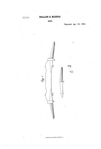
D.W. Phillip and W. Maher's Patent Drawing for Axels

National Archives, Restored Patent Drawings (Record Group 241) · Full-size scan at the National Archives · Catalog record
Text on the drawing
Words on the drawing as machine-read by the National Archives; not checked. Useful mainly for searching.
31 / 21. CARRIAGES & WAGONS. / {31] Axlez. / 5079-4 / Mouness Males / DIVISION / patented 23 april 1828 / His / Patent Office 28thApril 1838. / Madwinder direction of the Commissioner of Parents / in comformity with the act of s lanch 1507- / Commission & Faterity / A reen of the cast adxise both Arms secured: in the stock / A Bolls / B Bandi to Scouro the Aims in the Stocks / a at Collar made lo fit. the end.of the Arm not to / turn when the nut 25 screwed on / D A-rien of the before it is 72728 into the slock / 11 Nut to on the end of the aste
USPTO scan
The patent as scanned by the USPTO
-
 Page 1
-
 Page 2


U.S. Patent and Trademark Office · Google Patents
Published accounts: specification
Specification printed in the Journal of the Franklin Institute
Journal of the Franklin Institute, new ser., vol. 3 (1829), p. 349 · View the page
Text of the specification as printed in the Journal, from OCR; not proofread.
Specification of a patent for an improvement in the common carriage axle. Granted to DANIEL W. PHILLIPS, of Middlebury, and WILLIAM MAHER, of Covington, both in Genesee county, in the state of New York, April 23d, 1828. THE principal improvement here intended in the common carriage axle, consists in making the arm, or that part which works in the nave, of cast iron; to be constructed in the following, or a similar manner. Each arm of the axle is to be cast with a shank for securing it in the stock, and a wrought iron bar in the centre, projecting a little from the smaller end of the arm, on which is cut a screw to receive a nut for securing the wheel on the axle; the end of the arm is also a little depressed and squared, in order to receive a fixed collar, or washer, of the same circumference with the smaller or exterior box in the nave; after this collar is applied, the nut is firmly screwed up to it, and as the collar cannot turn on the axle, the nut is not liable to come off by the action of the wheel. The shank, which is square and tapering on the upper side, and of suitable length, is sunk into the under side of the stock, or wooden part, which connects the two arms and forms the central part of the axle, and is secured by bands and bolts. The benefits which it is supposed will result from this improvement, in the construction of carriage axles, are, 1st. They can be made at considerably less expense, than those of wrought iron. 2nd. Cast iron being harder, and wearing away much slower, than wrought iron, they will be more durable, and subject to less friction. 3d. By means of the fixed collar, the internal part of the nave is so effectually closed, that no dust or sand can insinuate itself into it. DANIEL W. PHILLIPS, WILLIAM MAHER. B e f d d C C A The figure represents one half of an axle, and shows the manner in which the arms are attached to the stock. A, the stock composed of wood. B, the arm framed into the stock A, and secured by the bolts c, c, and a band, seen at d, d. e, a bar of wrought iron, cast into the centre of the arm, and terminating in a screw f. This piece may extend to any depth. Specification of an improvement in the mode of making, or manufacturing, carriage bodies of every description, and of any required shape. Denominated Self-bracing Bodies. Granted to JESSE REEDER, of Lebanon, Warren county, Ohio, March 4th, 1828. 1st. THE skeleton of the body is formed of tough timber, or iron, made into bows or slats, which, for an ordinary sized coachee body, are about half an inch in thickness, and from a half to an inch and a half in width, when formed of wood, and of a corresponding strength; when iron is the material employed, these slats (of a length to correspond with the length, breadth, height and shape of the body required) are laid down, crossing each other at right angles in the bottom, at from two to ten inches apart, (according to the degree of strength required,) and are fastened together by rivets, screws, or otherwise, where they cross each other in opposite directions. 2nd. The raves or rails for the seats, and top of this body, being of tough timbers, may be so bent as to constitute, in one piece, the sides and ends of the body, so as to turn the corners with a curve, or with a greater or less angle, as desired; or they may be joined together in the usual methods at the corners. It may be here recommended that the bows and rails be steamed, and formed on sets, or moulds, of any desired shape, to suit the fashion of the body intended to be made. 3d. This skeleton when completed, may be enclosed by boards, or with leather, canvass, or other materials in general use; suiting the material to the curvature, or shape of the body. Pannels, if desired in the sections of the body, as also representations of a sunken bottom, may be formed of wooden or plated mouldings, or of any other desired material. 4th. It has been thought necessary by the inventor, in order to render his explanations more explicit, to mention in them, many of the component parts of those bodies now in general use. In this improvement, he, however, claims the sole prior right to the discovery, invention, and construction of the skeletons, of his "self-bracing bodies," by forming them of slats of wood or iron, so disposed as to extend in single pieces lengthwise the whole length and height of the body; in the same manner extending crosswise; and being fastened together by screws, rivets, or otherwise, where they cross each other at right angles in the bottom. Also, to his method of binding and applying the seat and top raves or rails, for binding the ends and sides of the slats, so as to render the desired shape of the body complete. The particular advantages proposed, in adopting this construction of carriage bodies, are, that they are found to be but of about one-fourth the weight, much stronger, less liable to external injury, and requiring not more than one-fourth of the time, manual labour, and expense in materials, that are necessary to the construction of any bodies now in general use. JESSE REEDER. On the causes which produce, and the circumstances which affect, the Draft in Chimnies; intended as an answer to the queries of " A Citizen of New Jersey," inserted in the Journal of the Franklin Institute for March, 1829. TO THE EDITOR OF THE JOURNAL OF THE FRANKLIN INSTITUTE. SIR, I submit for insertion in your Journal, the subjoined replies to some of the queries of a citizen of New Jersey, which appeared in the No. for March. Yours, &c. MARCUS BULL. 1. Upon what principle does the draft of an air furnace depend? The "draft," or, more properly, the current of air through a chimney, is produced, in consequence of air possessing the property of expansion when subjected to heat, by which expansion its specific gravity is decreased. The column of air within the chimney when heated, dilates, and thereby becoming lighter than the surrounding air, it is forced to ascend the chimney by the superior pressure of the column of cold air, and thus the current is established.* 2nd. What effect will an increased height of the chimney have on the draft? In some cases an injurious, and in others a beneficial effect. The proper height of a chimney, to produce the most powerful combustion in the furnace, is governed by particular circumstances. If the furnace, or receptacle for the coals, be of large dimensions, and capable of producing great heat, and the chimney be constructed of materials which are bad conductors of heat, its height may with advantage be greater, than should be the case if the furnace be small, • Your correspondent may be assured there is no drawing about the matter, and, although it might sound rather oddly, it would be more correct to say that a chimney drives, or pushes well, than that it draws well. and the chimney composed of materials which are good conductors of heat. Chimnies are intended to enclose and convey away the gaseous products of combustion, smoke, &c., and to prevent their dispersal, so long as they retain sufficient heat to render them more rare than a column of the external air, equal to the contents of the chimney; hence, the propriety of constructing them of materials which are bad conductors of heat. The quantity of air passing through a well constructed furnace in a given time, will be proportional to the difference in temperature, or specific gravity, between the columns of air within and without the chimney, and to their height. In theory, we should suppose, all other things being equal, that the height of a chimney should be such that the ascending current would leave it at the temperature which would allow its specific gravity to be precisely that of the external air, as this would give the longest rarified column; but, as the temperature of the air both within and without the chimney varies almost constantly, experience suggests the propriety of constructing chimnies of such height only, as will permit the smoke, &c. to pass off whilst considerably rarified, under all states of the weather; but no experiments have been made to determine the precise difference in temperature at which the ascending column should be permitted to escape; and this, indeed, must vary with every difference in the nature of these products of combustion, dependant upon the more or less perfect decomposition of the air in passing through the furnace. 3d. If an increased height of the chimney increases the draft, what is the ratio? All other things being equal, the ratio of increase will depend on the materials and area of the chimney; but in all cases this latter must diminish as we increase its height, the first foot producing more effect than the second, and the fifth more than the tenth, &c. If the chimney be composed of materials which are bad conductors of heat, the included column will cool at a slower rate than if the materials made use of be good conductors of heat; consequently, the ratio of increase must vary through any given space. In like manner, the cooling of a large and a small column will be at different rates. From the results of Mr. Dalton's experiments to determine the expansion of air by heat, it appears that from 32° to 212° of Fahrenheit, every 45° of temperature produces an expansion of about 1, which will reduce the absolute weight of any given volume so expanded,; but as the products of combustion possess greater specific gravity than an equal volume of the external air at the same temperature, and as these vary, we cannot estimate the precise difference in the pressure of the two columns merely from their difference in temperature. 4th. What effect will an increase or diminution of the superficial area of the chimney have on the draft? If the passage for the aeriform products be too small to allow them to escape freely, the quantity of air which would otherwise pass through the furnace in a given time, is diminished, and the combustion is, consequently, retarded. If, on the other hand, the passage be larger than is necessary for their free escape, the sides of the chimney will also present a larger refrigerating surface, which reduces the temperature of the included air more rapidly, and, consequently, increases its specific gravity, by which the velocity of the current is impeded. To produce the most intense combustion, it is necessary that the furnace be perfectly supplied with air, and when that portion of it which may remain undecomposed, together with the products of combustion, shall have passed through the furnace, what is ordinarily called the draft, must be such as to force them to escape through the chimney with the greatest velocity, as that furnace which will consume the largest quantity of air and coals in a given time, must necessarily produce the greatest amount of heat; but no satisfactory experiments have as yet been made to ascertain the proportions which should exist between the various parts; hence data are wanting to proceed upon principle, and we can only accomplish the end in view by repeated trials. 5th. Will a chimney largest at its top, or vice versa, make the strongest draft? As that portion of the column of heated air, &c. nearest the burning coals, must necessarily be the most expanded, and require more room than at the top of the chimney, where their temperature and volume are diminished, a chimney largest at the bottom, must be better calculated to promote a rapid current through it, than the same chimney with its apex reversed. 6th. Is it important, as regards the draft, that the materials of which a chimney is composed, be good conductors of heat, or otherwise? It is very important that the materials be bad conductors of heat, that the included column of air, &c. may be cooled by the slowest process. The advantage of this has already been stated in the answers to some of the preceding questions. 7th. What is the best mode of binding the chimney of an air furnace, to prevent its cracking? This is a question so entirely practical, that the answer, to have any value, must be given by one who has had much experience on this subject: the writer of the foregoing replies will not, therefore, attempt it, but hopes that some liberal iron master, or founder, will afford the required information, which, whilst it may give strength to his neighbours' chimnies, will not have the effect of weakening his own. VOL. III.-No. 5.-MAY, 1829. 45 Observations on an apparatus to illustrate the Composition and Resolution of Forces, and to measure the power obtained by certain parts of machinery operating on this principle. By WALTER R. JOHNSON, Principal of the High School of the Franklin Institute. THE great number of operations in practical mechanics, which involve the composition and resolution of forces, renders it important that the calculation of oblique forces should be made familiar and easy. The proposition so well known in theoretical mechanics, under the name of the parallelogram of forces, does not appear to be sufficiently understood, since we occasionally find the strangest violations of its laws, in the constructions which artisans are called upon to execute. This circumstance has induced me to attempt to present the subject under such aspects as may free it from doubt, and enable the practical mechanic to understand and apply, at least in ordinary cases, the principles involved. To be convinced of the importance of this subject, we need only refer to the fact, that the supporting of bridges, whether on chains, timbers, or arches, is obviously dependenton the laws of equilibrium between oblique forces. Even the trussing of girders in common buildings, and the sustaining of arches, for whatever purpose, must be referred to the principle of resistance's applied in directions not parallel to that of the force which tends to produce motion, but with some degree of obliquity to that direction. Where intensity of action, and not extent of space, is the main object of a mechanical implement, the principle of oblique forces furnishes a variety of means for attaining the desired end. The common apparatus employed for demonstrating this subject, consists of three cords, joined at one point by a knot, at, or near the centre of a circular horizontal table; the free end of each cord passing over a pulley to sustain a weight. When the weights are equal, and the three pullies are adjusted at equal intervals round the circumference of the table, the knot remains at the centre of the table, and each angle formed by two contiguous cords, is, of course, 120°. By varying the weight on one or two of the cords, different angles may be formed at the point of union; but, in this case, if we would preserve the knot at rest in the centre of the table, the posi tions of all the pullies must be changed with each variation of weight. In all cases of equilibrium, the weight attached to each cord, or, what is the same thing, the tension sustained by it, will be in proportion to the sine of the angle formed by the directions of the other two. If, instead of cords attached to a fixed point, or, what is the same thing, fixing their knot to a given point in space, by their own equilibrium, we suppose the two ends of a cord to be attached to two fixed points in the same horizontal line, and to hang somewhat loosely between them, and that a weight be suspended to this cord by a On the Composition and Resolution of Forces. pulley, ring, or sliding knot, so as to pass easily from one part of the cord to the other, then the weight will find the lowest point to which the cord will allow it to descend, when it hangs in the centre. The two parts of the fixed cord will then be of equal lengths, sustain equal tensions, and form equal angles with the vertical direction of the line which supports the weight. Now the force which stretches the fixed cord, represented in the figure below by the two weights W and V, may be conceived to produce two different effects, one tending to bring the pins, or hooks, to which it may be attached, nearer to each other, and the other to bring them downwards in obedience to the gravity of the weight. These two effects may be represented in amount by the respective lengths of a vertical and a horizontal line meeting at a point perpendicularly above the pulley to which the weight is attached. The figure annexed will render this intelligible. W E A D B C P If the lines CA and CB, be supposed to represent inflexible rods, and the points of attachment A and B, be capable of sliding along a rod, or wire, towards D, then the weight P remaining always the same, the two wires CA, CB, must sustain the same tension as when they were flexible cords; but the resistance to a horizontal motion in the direction AD, or BD, is what we have to measure. The tension of CB produces two different effects, one in the direction DB, the other in that of DC; and the lengths of these two lines respectively express the intensities of the forces into which CB is decomposed. But as CB is always of the same length, whatever its inclination to AB, it may be taken as the radius of a circle, and then DB becomes the cosine of the angle CBD, but the sine of DCB, or of its supplement PCB; and DC is the sine of CBD, but the cosine of DCB, or of its supplement PCB. The effect of the tension of CB towards sustaining the weight P, is, therefore, expressed by the line CD, or the sine of the angle of depression of the wire CB. But the tension of CA produces another similar effect, and to the same amount; of the two, therefore, the sustaining force is expressed by the double of CD, or twice the sine of the angle of depression. This is represented by DE, the diagonal of the parallelogram AEBC. If we suppose the points of attachment, A and B, to be prevented from approaching each other by cords passing over pullies at some distance from these points respectively, but in the direction of AB produced, the weights which would be required to retain the points in their present positions, would be, to the weight suspended at C, as the length of AD, and of BD, respectively, to the length of DC. But these two lines have to each other the relation of the cosine to the sine of the angle of depression, and these two quantities will vary with every change of the angle, so that when one of the forces is constant, it becomes necessary for convenience in practice, to substitute for the relation of cosine to sine, its equal, viz. that of radius to the tangent of the angle of depression. We may readily perceive that when the two wires are brought into a horizontal position, as there is no angle of depression, there can, of course, be no tangent, or the tangent will be represented by zero; whence the weights which draw the points A and B apart, must be to the weight which is suspended at the centre, as a finite quantity to one infinitely small, or nothing. Or if the weight hung upon the centre be of finite magnitude, the forces which draw the points A and B apart, must be infinitely great. When, on the contrary, the two wires, AD, BD, come to a vertical position, the angle of depression is 90°, whose tangent is infinite. The relation, therefore, between the radius and tangent, is, in this case, indefinitely great. The whole weight is sustained by the horizontal rod to which the others are attached, and no force, however small, can be applied in a horizontal direction, tending to
Published accounts: journal notice
Notice in the monthly list of patents
Journal of the Franklin Institute, vol. 6 (1828), p. 140 · View the page
In the common carriage axle; Daniel W. Phillips and William Maher; the first of Middlebury, and the last of Covington, New York, April 23.
Published accounts: journal notice
Notice in the monthly list of patents, with remarks
Journal of the Franklin Institute, new ser., vol. 3 (1829), p. 348 · View the page
THIS machine is a reel or cylinder, of dimensions suited to the vat in which it is to be used; it consists of two or more cylindrical wheels, either solid or otherwise, placed at certain distances apart, and properly framed together, with a shaft, or axis, passing through their centres, having gudgeons, on the extreme ends, to rotate upon; they are also connected together by four, or more, laths, extending nearly the whole length of the axis; which, when attached to the outer surface of the wheels, may properly be called the reel. At the head are fixed four handles to turn the reel by, or it may be turned by other means; it is to be supported by a slide at each end of the axis or shaft, which works in the lower end of the slides, and can be lowered and raised, at the pleasure of the workmen, and supported by pins passing through the slides into cleats on the surface of the vat; on the outer surface of each wheel, are short thongs of leather, having both their ends fastened by pinning them into holes about one inch, more PHILLIPS and MAHER's Carriage Axle. or less, apart: these loops pass into holes made in the edge of the hides, skins, &c. and the loops pass through each other, and form a connexion which keeps the hides, skins, &c. to their proper place; or, in lieu thereof, there may be hooks of a curved form, firmly fixed; the hides, skins, or whatever is to be tanned, is to be attached to the surface of the reel, expanded in full width, supported by the loops or hooks; the hooks to be used when liming or bating the surface of the reel, may be fixed from three to six inches under the liquor; in the process of turning the reel forward and backward, it changes the position of the hides, &c. in such a manner as to cause every part of the hide to come in contact with the liquor. This machine surpasses all others in its principle of sinking to the bottom of the vat, when left at rest. WILLIAM BROWN. Specification of a patent for an improvement in the common carriage axle. Granted to DANIEL W. PHILLIPS, of Middlebury, and WILLIAM MAHER, of Covington, both in Genesee county, in the state of New York, April 23d, 1828.
Remarks. THE principal improvement here intended in the common carriage axle, consists in making the arm, or that part which works in the nave, of cast iron; to be constructed in the following, or a similar manner.
About this record
- Patentee
- DATAMP
- Date
- the Name and Date index of patents, DATAMP, USPTO records
- Invention
- DATAMP
- Listed in
- the Name and Date index of patents, DATAMP, USPTO records, Jim Shaw's X-patent list, the Journal of the Franklin Institute, the Mirror of the Patent Office (1828), S. A. Elliot's printed list of patents, Burke's List of Patents (1847)
- The Mirror of the Patent Office's supplementary list gives the same patent.
- S. A. Elliot's printed list of patents gives the same name and date.
- in_burke