

Drawings and documents
National Archives restored drawings: drawing
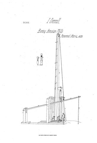
Unknown Patent Drawing for a Machine for Boring Rocks

National Archives, Restored Patent Drawings (Record Group 241) · Full-size scan at the National Archives · Catalog record
Show the text on the drawing Hide (75 words)
Words on the drawing as machine-read by the National Archives; not checked. Useful mainly for searching.
Rucks / botty ly / Patented. / 5036-1 / A Part of Frame to Support Timber B. / B' pegs to climiti the / C. Windin/s with Which nasses over be whached to Pincers D / D. Pincers / Boring Rod / Suring. ff Frames / a. Block, Peice of rvood, Re Pulley with Tope attached to Shring e Treadle / H. Treadles / 15 Riminer / of / Made muder the direction
USPTO scan
The patent as scanned by the USPTO
-
 Page 1
-
 Page 2


U.S. Patent and Trademark Office · Google Patents
Show the transcription Hide (139 words)
Machine transcription (LightOnOCR) of the pages as scanned by the USPTO, most of them the handwritten copies made when the records were restored after the 1836 fire. Not checked; it can misread handwriting, so compare it with the scan.
Page 1.
5036X
I. Overall,
Boring Artesian Wells.
Patented Mar. 14, 1828.

A.M. PHOTO-LITHO. CO. N.Y. (OSBORNE'S PROCESS)
Page 2.
United States Patent Office
PTO - BOYERS, PA Duty Station
MISSING PAGE TEMPORARY NOTICE
PATENT # 5036X FOR ISSUE DATE 3-14-1828
HAS BEEN SCANNED, BUT WITH MISSING PAGE(S). UPON RECEIVING OF MISSING PAGE(S), THE ENTIRE DOCUMENT WILL BE RESCANNED.
PLEASE CALL IMAGE DATA ADMINISTRATION STAFF OF 557-6154 IF YOU HAVE A QUESTION. ASK FOR DAVE GROOMS, ANITA YOUNG OR POLA JONES.
THIS NOTICE IS FOR THE MISSING PAGE CONTAINING:
COLUMN # All Text
Data Conversion Operation
Boyrs, Pa
Published accounts: specification
Specification printed in the Mirror of the Patent Office (1828)
American Journal of Improvements in the Useful Arts, and Mirror of the Patent Office, vol. 1 (1828), printed p. 180 · View the page
Text of the specification as printed in the Mirror of the Patent Office, machine-transcribed from the page scans (GLM-OCR); not proofread. Check the scan for figures and reference letters.
By Israel Overall, of Smith county, Tennessee.
Specification.—I first construct a frame of sufficient size to sustain the weight of a timber, or it may be a superstructure forty-two feet in height, more or less, and to suit the convenience of those employed in boring. On each side of this beam, or timber, I insert a number of pegs, about two and a half inches in diameter, at suitable distances apart, and in every way calculated to permit the climbing of the superstructure, or timber, with ease.
On the top of this timber, I place a wheel, or pulley, over which a rope passes, which rope is wound around a windlass, which I construct in the centre of the frame, above described. After passing over the wheel, or pulley, the rope is attached to a pair of large pincers, or forceps, in such a manner as to enable the person employed to elevate the boring rod from the depth to which it may have been sunk by the operation of the machine.
This rod is situated at a small distance from the foot of the above specified timber, elevated above the frame. One extremity of the rod passes through the nearest end of the spring, and is there secured by a ring and nut. This spring is about twenty-eight feet in length, more or less, and is made of any suitable material; but the wood that possesses the most elasticity is the best for this purpose.
The other extremity of this spring is held in a small frame, constructed for the purpose. It consists of three pieces of timber for a sill, or ground frame, upon which two pieces are built in front, seven inches apart, and about twelve feet in height, with a number of holes passing directly through both; through which holes I pass a pin, upon which the spring rests.
At about the distance of twelve or thirteen feet behind these two pieces of timber, another is constructed; this piece is seven feet in height, more or less; through the top of it I cut a mortise, into which the extremity of the spring is loosely received; a round pin is passed through both, which admits of the elevation and depression of the spring. The construction of this frame I claim as part of my invention.
At the other end of the spring, I make several holes, so as to vary the position of the rod at pleasure. The rod thus fastened in the extremity of the spring, is ready for the operation of boring, which is thus effected:—About four feet above the frame, a hole, or it may be two, at a small distance apart, on the frame, are mortised through the timber or superstructure, as may be; through which a block is passed, that receives through it the upper extremity of a small piece of wood that holds in its lower end a wheel or pulley, around which a rope is passed. This rope is fastened by means of a chain and hook to the spring and lower sill, to two tread planks, about six feet in length, passing from one side of the first described frame to within a few inches of the other.
These tread planks are guided in their direction, between three posts perpendicularly erected, by pressing alternately with the feet on these two foot boards, the spring is drawn down and consequently, with it, the rod. Two pieces of timber are attached at a proper distance from above, the loose extremities of the tread boards just described, upon which the person sits and rests himself in the act of treading or boring.
When the rod is to be drawn out, the pincers above mentioned, are closed upon its upper extremity, after all things above are removed, which is easily done, and the windlass is turned by means of the crank, the rope, passing over the first described timber, is wound around the windlass, and the rod elevated. The windlass may be checked at any time by a counter latch.
In case the rope should be removed, or slip from the wheel or pulley above, the timber being easily climbed, it can be adjusted without delay.
If it be necessary to bore a larger hole than can be made by the long and stationary rod, a small piece of steel may be easily screwed on the lower extremity, to enable the workman to bore a much larger hole than is effected by the main rod; and this is done at a very trifling expense; the additional piece of steel, that is thus screwd on, is only seventeen inches in length, or thereabouts, and just above the centre of this piece, it becomes broad, of a breadth to bore a hole large enough to suit the person employed. As it grows broader in the centre, it also becomes thinner, gradually, until it terminates in an edge, sufficiently sharp to cut the rock. This piece is screwed above, into the lower extremity of the rod, by the male and female screw.
After being made of a sufficient breadth in its centre, it again becomes about the size of the rod, and is made round; and, finally, it becomes larger at its lower extremity, than at the bottom of that part of it where it is the broadest; by this means a hole of any required diameter can be bored. The upper and lower extremity of this last mentioned piece of steel, or rimmer, may be separated at pleasure, in the centre, where it is united by means of a rivet, which can be easily driven out. The two frames, instead of being separated, or at a distance apart, may be united, as the operator may wish.
Instead of the three holes, above mentioned, being in that extremity of the spring to which the rod is attached, they may be situated in the extremity that is connected to the second frame described above.
What I claim as my own invention is, 1st. The construction and application of the perpendicular timber, forty-two feet in height, and all that is applied thereto, for the purpose above specified. 2d. The application of two tread boards, instead of one, as commonly used. 3d. The mode of attaching the rod to the spring, with the peculiar mode of constructing that part of the spring nearest to the first described frame, that is, about five inches of the spring at this extremity. 4th. The construction of both the frames above described. 5th. The quoins connected with the tread boards; and 6th. The rimmer, or last described piece of steel, for increasing the diameter of the hole to be bored. Instead of only using one pulley and two treadles, five pulleys may be used, with four footboards; the former, I think, is the preferable mode.
In testimony that the above is a true description of said improvement, I have hereunto set my hand and seal, this 4th day of February, A. D. 1828.
ISRAEL OVERALL.
C. H. W. WHARTON,
JNO. B. ELLIOT.
Witnesses.
Date of the Patent, March 14, 1828.
Published accounts: journal notice
Notice in the monthly list of patents
Journal of the Franklin Institute, vol. 6 (1828), p. 72 · View the page
In the machine for boring rocks, Israel Overall, of Liberty, Smith County, Tennessee, March 14.
About this record
- Patentee
- DATAMP
- Date
- the Name and Date index of patents, DATAMP, USPTO records
- Invention
- DATAMP
- Listed in
- the Name and Date index of patents, DATAMP, USPTO records, Jim Shaw's X-patent list, the Journal of the Franklin Institute, the Mirror of the Patent Office (1828), S. A. Elliot's printed list of patents, Burke's List of Patents (1847)
- The National Archives' catalog gives the name differently.
- The specification was printed in the Mirror of the Patent Office (1828).
- The Mirror of the Patent Office's supplementary list gives the same patent.
- S. A. Elliot's printed list of patents gives the same name and date.
- Burke's 1847 Patent Office list gives the same patent.