

Drawings and documents
National Archives restored drawings: drawing
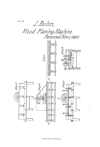
Josiah Reihm's Patent Drawing for a Planing Machine

National Archives, Restored Patent Drawings (Record Group 241) · Full-size scan at the National Archives · Catalog record
Text on the drawing
Words on the drawing as machine-read by the National Archives; not checked. Useful mainly for searching.
143. WOOD WORKING. / 2. GENERAL WORK MACHINES. / [173] Planing. / classlication / JOS IAH REIHMS. / 4914-7 / PLANING MACHINE / Nov, 1.1827. / patented 1 nort 1827 / Fig / Scale. / Fis B / Iis C / FigDt / NOTES of REFERENCE / Fort the ground plan. Sections and elevations of the Dohable faced Rotary Plane / adranced / Fig B Fig:A (c) Ground Elevation plan. of me side Shewing The loweror bearing carriagenta open advanced view nuth the Fig cris sliding uncovered carriage of its top / forward inch plank as tig only In its them intervor its. Graming parts- / and open to view / FIGD section through CD in Tig B sharing its interiorparts also, with a shaft with pulley's / Isa section cutthrough AB 2.27 (ThgB: Sherring / lsa thereon, for a circular to slip one the affords many advantages
USPTO scan
The patent as scanned by the USPTO
-
 Page 1
-
 Page 2


U.S. Patent and Trademark Office · Google Patents
Published accounts: specification
Specification printed in the Mirror of the Patent Office (1828) with its plate

American Journal of Improvements in the Useful Arts, and Mirror of the Patent Office, vol. 1 (1828), printed p. 159 · View the page
Transcription
Machine-read text of the specification as printed in the Mirror; not proofread. Check the page scan for figures, reference letters and spelling.
me res IMPROVEMENT IN THE PLANING MACHINE. > ae ee Sea Reihm, Savage Factory, Anne Arundel County, Maryland. ear ~“s ee : See plate XV. figs. 1 to 6. ES Specif ification.—This planing machine is principally composed a and framed of good seasoned wood. There is a substantial frame, box, or table, on which this plane is supported, as will ee appear in the draft; the lower part of this frame, box, or table, whe projects under the bearing carriage, inorder to support the connection, by bolting the bearing carriage on the projecting pari; on the bearing carriage there is a sliding carriage, whereon the ak materials are fastened. This’ sliding carriage is also framed of ee ‘good. seasoned wood; there are sides to it, and cross pieces framed into them, and bolted together, to form this carriage; eS upon the top of which, is what I call a moveable fence, secured ae by means of screws, the heads of which work in grooves cuttin the inside of the cross pieces, which secure the sides of the car- eS Mage. _ The pieces are kept apart the thickness of these screws, aa to admit the screws with the fence to move in and out on the ‘Sr top of the carriage; the fence has also grooves, in the inside,of a: with similar screws, to admit of moving forward and back- oS ward with the overheaded bites, or hold-fasts, that bear on the Ey back or upper edge of the carriage, with one end of them to Sa counteract the end that holds the material, or timber, that is, to a bewrought. The carriage moves on slides with the material yl a in contact. with the plane; the material that planed passes close by the side of the plane, and. by the side of the carriage, in front, and opposite the revolve; the attendant is to stand and to put on and ie off the materials. Previous to starting the machine, it ought to be well oiled in all its bearings, and then be put in operation by whatever power is most convenent. - The sliding carriage I used to put in motion by hand. Sa a ao a ESS ere een SE Te ke ee eo ae " — m9 ee pg itt amt as =a eS Meise af. 5 tatane tan Be _ (No. 1.) The principal claim and points on whic h the merits ‘hee or ‘my original invention rest, are the sliding carriage, as dese cribed, and the bevelled angle face, or a segment of acircle,or Be either of the two, with common flat bits, or cutters, ground to 4 A _ suit any of those faces. That is, the bevelled angle face, or any : ‘other formed face, in the same position of this bevelled angle face. The bits, or cutters, pass through from the rear, and are . a wedged fast with wedges similar to the common kind of plane “wedges. Instead of bent knives, spoke shaves, or deep cutting fac: gouges, flat bits, or cutters, are employed, when ground to suit either of those faces, for cutting off the roughest part. S (No. 2.) The above, from No. 1 to No. 2,1 would have understood as my original invention. The vertical face joined to the bevelled angle face, and bits passing through from the rear to suit it, follows the former in succession under the same oper-_ ation, which latter I call a smoother, or jointer face, as itis the i _ last in operation, and the nearest to the axis, and of course a a little deeper than the former; it cuts the last part left. This 4 a double faced rotary plane is fastened on the end of a shaft, lying horizontally, resembling the mandrel of a common turning Iathe, and is operated by a pulley in the same manner. The different faces of this plane are so arranged as to fall in contact with the wood or other materials to be cut. The bevelled face Bs. will cut first, and take off the rough and prominent part, and the vertical face will reduce the material down to the line intended for the surface. ;
fg I have prepared a model of this planing machine agreeably to the original, with some improvements made since. You will find, instead of a plane, as before described, No. 3, I have a K eae cast plate of metal, resembling a dining plate, and not more, perhaps than half an inch thick, it may be more or less in thick- __-mess. This plate.is concave in the rear of the face, and has oan beds whereon the bits or cutters are confined; these beds have __ Be - screws fastened in the middle of each, projecting out, inorder to hold the bits, or cutters. There are caps and nuts on the top of these bits, or cutters, whereby they are confined. The caps : a bearing on the bits, with the nuts screwed fast; these bits, or a> cutters, are fixed on the swivel principle; that is, when one part of the bits become dull, the nuts may be slackened, and the bits ie turned on a swivel, which will bring in the dull parts of them, oo and forward the sharp parts; this will save much time in regard to sharpening. py fat E.. This plane will work with bits, or cutters, from one to seven inches wide. The segment part, instead of the bevelled face, is ps calculated for bits of seven inches or more in diameter; bits of a almost any width under: seven inches will answer, by grinding ; them to suit the segment; and the fore and jointer bits havetwo if a eae ee ee ee art s PD, | Semen oe “5 Co eee a ee re oe ka eT a ee”. a Fs si liy ale. acca edges to each of them; that is; each bit, on its edge, is ave “a info two parts, so that when one edge becomes dull, the nuts ie may be sh ackenet , and the bits turned also on the swivel prin ae have al mop ye the sliding carriage, by iron gauges that as pass through the fence and stand perpendicular to the top of the — eh, arriage; they fasten with thumb screws, and are ready to set incor out, to suit “any Ikness, or width, parallel or wedge | eau There is a range of small holes in the front side of the carri- tik ait “age to suit any length of stuff. By taking out a pin that fits aX. ae the holes, and putting it intoanother that ismearer the back endof F _ the material to be wrought, will cause the carriage to return, Ri a (No. 4.) From the above, No. 3 to No. 4, includes and has reference to my additional improvements. Ihave also appheda feed motion, that conveys the sliding carriage forward and backward, and will stop while the plane continues revolving. The = 8 attendant has to put the material on the carriage, and screw it fast with overheaded bits, and to pull the trigger, which will immediately put the carriage in motion. Y aa PS SER as Nieves tas eta ..... JOSIAH REIHM., WILLIAM THORNTON, } Hilibiaes =e SOS Sue Si Ay ELLIOT; 4-25 SS; Ta eS ta bie Date of the patent, November'1, 1827. aa ) od SHES oc wae
[References to the plate, as printed:]
ee | Woe car REFERENCES.-——PLATE XV. ae a :
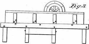
og : Fig. 1. Perspective view. " aS BO “A Supporting box, or table. oe ‘BB Bearing carriage. > ee Sliding carriage. Beatie Side of the bearing carriage for supporting one end of the slides. ee Moveable fence, with screws to change its position in the grooves: Sk ae FF Overheaded bits, or headfasts, to confine the material to be planed. _ SS. Se
Published accounts: journal notice
Notice in the monthly list of patents
Journal of the Franklin Institute, vol. 5 (1828), p. 212 · View the page
In the planing machine; Josiah Reihm, of Savage Factory, Maryland, November 1.
DATAMP: illustration
Illustrations from DATAMP

DATAMP (Directory of American Tool and Machinery Patents), via the Internet Archive · Archived DATAMP page
About this record
- Patentee
- DATAMP
- Date
- the Name and Date index of patents, DATAMP, USPTO records
- Invention
- DATAMP
- Listed in
- the Name and Date index of patents, DATAMP, USPTO records, Jim Shaw's X-patent list, the Journal of the Franklin Institute, the Mirror of the Patent Office (1828), S. A. Elliot's printed list of patents, Burke's List of Patents (1847)
- A drawing was printed in the Mirror of the Patent Office (1828).
- The specification was printed in the Mirror of the Patent Office (1828).
- The Mirror of the Patent Office's supplementary list gives the same patent.
- S. A. Elliot's printed list of patents gives the same name and date.
- in_burke