

Drawings and documents
National Archives restored drawings: drawing
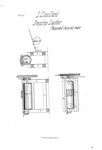
S. Couillard, Jr.'s Patent Drawing for a Machine for Dicing and Polishing, or Rolling Morocco Leather

National Archives, Restored Patent Drawings (Record Group 241) · Full-size scan at the National Archives · Catalog record
Text on the drawing
Words on the drawing as machine-read by the National Archives; not checked. Useful mainly for searching.
Finishing / 14 / Witness / YAl. b. leage 419 / fy for / So COUILLARD JJ / you / Diringlephisting / 4801-4 / Palented any "June 132% / DIVISION. / clide sectran / cross / 7 7 e 0 a 9 / Rey 0 / A. Frame / B. Hollam cylinder. b. Slenftofn" / plan / C. Lanchetmarine / D. Rails / carriage e Pummels / F. / a Lever / H. Azm mith / HEP / I. Ity 07 operating pulley / H. Firection whert / I Zever forming a Taugent with / M. Iron-her with " counding and pressed / in 07 out by a wedge attached to side of Leverl. / N. Countring nin / Patent office lung 31.1840 / Madeunder the direction of the commissioner / Del) / of nature in conformity with acto 3"March 1337 / Commission of patents)
USPTO scan
The patent as scanned by the USPTO
-
 Page 1
-
 Page 2


U.S. Patent and Trademark Office · Google Patents
Published accounts: specification
Specification printed in the Mirror of the Patent Office (1828) with its plate


American Journal of Improvements in the Useful Arts, and Mirror of the Patent Office, vol. 1 (1828), printed p. 169 · View the page
Transcription
Machine-read text of the specification as printed in the Mirror; not proofread. Check the page scan for figures, reference letters and spelling.
POLISHING AND DICING, OR ROLLING, MOROCCO LEATRER. = af By Samuel Conillard, Jun. of Boston, Massachusetts.—See plate XVII. figs. 4 &5. mee. Specification —The frame of this machine is built of joist oes about four inches square, and is of a quadrangular or square form, being about five feet in length, three feet in height, two Roar feet four inches in breadth, having four posts, one at each cor- as ner, standing perpendicularly in the. frame; the ends of these Ra. posts are tenoned into other pieces of joist, which lie horizon- Be tally, crossing the frame at the top and bottom in eachend. "These, with the posts, form each end of the frame. am ee Two. pieces are tenoned into the two front posts, one about five ‘inches from the bottom, and the other the same distance from the top; the two back “posts are connected in the same’ a manner. A hollow cylinder, about four feet in length, and ae eighteen inches in diameter, having a smooth surface, and’ mad of smooth hard wood, or some suitable metal, is horizontally ee placed, lengthways of the frame, in its upper part,‘and is there ae secured to a shaft which passes through its centre. This shaft bE: is placed in metal boxes near each end, on the upper surface of = 3 each end of: the frame, near its centre, between the front and back side thereof. A space is made in this cylinder, runn ee Was th ea Be Santo sys ; Sa Sehce ae te : ex SE ona Reet. S203 Rea whole length, about six inches wide, for the purpose of hanging eNten therein a Jatchet or gripe, which swings inward upon hinges, on Ka. its back edge, and which fills the said space completely, when nag pressed outwards by means of springs, and is kept back by a a”. catch that has a thumb piece or pull affixed to it to disengage it from the latchet. Over the cylinder are placed two stout iron bars, which are called the rails, running the whole length of the a frame, and lying parallel with the cylinder, and at a distance from each other of about ten or twelve inches, and each at an equal distance from the shaft, with their under surface about level with the upper surface of the cylinder; these bars are, “8 supported at each end upon the frame by a stud of iron firmly fastened to each. ;
From the imer side of the lower edges of these rails is projected a ridge or flange, which runs the whole length of them, being about half an inch square; to these ridges is fitted a rm carriage of a quadrangular form, and about ten or twelve inches square, composed of four iron rods or bars, or it may be cast in a the same form. The front and back sides are placed on the is inner sides of the rails, about level with the flanges or ridges; the other two sides or ends of the carriage are made or bent into an arch, and lie directly over and at right angles with the ag cylinder, leaving a space between them and the cylinder of about eee one half of an inch. ‘The ends of these two sides pass by the ends _ of the other two, to which they are firmly attached, and are fitted at their ends to the ridges or flanges, by a notch in their ry ends, corresponding with the form of the ridge, on which the carriage rides from one end of the machine to the other, and having in itself no other motion. In this carriage are placed the pummels or polishers, being about three or four in number, yg which are in the form of a section of a cylinder; their position a in the carriage is side by side, forming a line lengthways on its upper surface, in the centre of the carriage, between its front a and back post, their periphery being parallel with that of the cylinder, the diameter of the polishers is equal to the length or a measurement across their periphery, the diameter being from am two to four inches; they are turned with small parallel creases around them, on their periphery, and are made as smooth as possible; they are each secured in the carriage by an iron hoop bee of a square form, which I term the stock, and which corresponds es with their shape; from the back part of each of them extends an iron arm, running to the back bar of the carriage, on which ae it forms a joint so as to allow the polishers to rise and fall to and from the cylinder, on which they are pressed by means of springs or weights attached to the carriage. An arm which runs from the front part of each stock, extends partly over the a front bar of the carriage, on which it rests when the polishers: eee eee Se ae et 4 Bi ee RE OM ee Mn Ne We ORME ilk. iil ale iat Sale ti "y AMBRICAN JOURNAL, eS ae Bac” ay a hae Bb asta, have no bearing on the cylinder. When this machine is operating, i ie the carriage is caused to move from one end of the rails tothe other, having a motion similar to that of the carriage ofacommon saw mill; this is effected by means of a flat iron bar placed Bs horizontally upon the inner side of the back rail, with its edge re) passing through guides at each end. The lower edge of this bar is formed into teeth, similar to those of a saw; these og teeth operate upon a ratchet or hand, which is affixed tothe back part of the carriage; this bar is caused to vibrate back and forth - mat endways, by means of a lever, the upper end of which formsa joint with the end of the bar at the left hand of the machine, and the lower end of the said lever falls in contact with a camb that Sante is fastened to the outer side of an arm that leads off at a right Bas: angle from the end of the shaft of the cylinder, which is caused SS to revolve backward when the machine is operatmg. This lever operates upon a joint in its centre, and is hove outward at ae its lower end by the camb, and returned by aspring; thus giving Ba: the carriage a motion as before described. One end of the shaft, which passes over one end of the frame at the right hand,extends beyond it about nine inches. Three inches of the outer ae end of this section of the shaft, is made round, and passes through es the centre of the fly or operating pulley, which is about three a feet in diameter, and which is caused to revolve by means of a ota band. This pulley has a hole in its inner side, six inches from Oe its centre, to receive the outer end of an iron pin, which I call ae the coupling pin, which is placed horizontally, parallel with the shaft; this pin passes freely through a hole from the inner to the ae outer side of an iron wheel, which is fourteen inches in diameter we and one inch in thickness, called the friction wheel, through oy which the shaft passes in running from the end of the frame to acd and through the operating pulley. This wheel is firmly fixed es to the shaft, and is placed near the inner side of the fly pulley, oe, for the purpose of coupling them together with the coupling a pin, which causes the cylinder to revolve with the fly pulley. er: For the purpose of disengaging the fly pulley from the friction ea whee], the pin is started inwards towards the end of the frame, relieving it from‘the fly pulley, which continues to revolve Sou while the cylinder remains stationary. This is effected by as means of a lever which is placed across the end of the frame at Se: oH: _ the right hand, forming a tangent on the top of the friction — Re: wheel; a piece of iron at its lower end is made fast to the back part of this end of the frame, the upper end of which formsa joint _- with a part of the lever that is.near to its back end; thisjomtis so formed, as to allow the lever to rise and fall to and from the a friction wheel. On the inner side of this lever, near the centre, between the two ends, is projected a wedge, with its point to- — = aa wards the front end of the lever; che imer side of this wedge rs F. aa % ' fe me F pai) ey at Pu s eS : ee ae x ‘ i % x Ra “Bh SOE ar oon ‘ j : et as a SS a Oe Pets. * bs agi ian oe oe Rees Ke See :
“ae a ae: ‘ Soe Soe ES Se eee Serre, *Bh5 Rie NO ED: Sates Ts 5 a ee Me ET CMR | EP Me aptn eee “ee oe phy ay ; : iN Ree receives the upper end of an iron bar, which is attached near its er upper end to the inner end of the coupling pin, and runs down a on the inner side of the friction wheel, forming a part of a circle, . ___ to enable it to pass the shaft, and forms a joint near the lower edge of the friction wheel, to which a part of the joint is attach- ‘eat ed, and-consequently revolves.round with the friction wheel; aes this bar is pressed against the inner side of the friction wheel by F "oe means of a spring, and pressed off by the wedge on the lever— po a weight on the back end of the lever causes it to rise, when disengaged from a catch at its front end, and consequently raises the wedge above the end of the bar to which the coupling pin is fixed. The bar which passes the outer end of the * against Ky the inner side of the fly pulley, and slips it into the hole in the fity pulley, causes the cylinder to revolve with it, it being hove eines: into gear. In order to heave it out, and stop the cylinder, the hes latchet in front of the lever is pressed down with the hand, By! which applies friction to the wheel, retarding the motion of the : a cylinder previous to its being thrown out of gear; this takes place as soon as the projecting end of the bar arrives apes the Be”. wedge, which heaves it towards the end of the frame and draws ie the pin from the fly pulley. In order to avoid the casualty of the ke friction not being sufficient between the lever and friction wheel 4 fe to stop the cylinder in its desired position, I project from the ben back end of the wedge a stout cog, pointing inward towards the ee end of the frame, which receives the end of the bar and stops 5; the cylinder at once with the latchet in front. ae The skin being prepared in the usual manner for polishing, is now placed upon the cylinder, with its grain upwards, or outwards, placing nearly one half of it in the cylinder, through the ay space where it is firmly secured by the latchet, and the machine ey being hove into gear, causes the cylinder rapidly to revolve, while-the skin lies flat to the cylinder. The polishers are pressed down in manner aforesaid upon the skin while it is. moyes ing with the cylinder, and when the skin has passed from under them, the carriage moves by. means of the teeth and ratchet in a direction from one-end of the machine to the other, so that every a a part of the skin is successively brought under the polishers. If af we more than one set of lin s are required on the skin, it is done by angling the skin on the cylinder, and carrying the polishers to h, operate upon it as before. After finishing that part of the skin a which was left out of the cylinder, it is taken out, the finished ee part of it is then put into the cylinder, and the remainder of the 3 nee skin is mn sagen upon in the same manner. dip) ve In order to give the skin a smooth polish, without any figure, polishers without creases are made use of. When the carriage a has moved from one end of the cylinder to the other, by the operation of the machine, it is carried hack by the hand of the heal Me Sau ail aa nM cass” ANE Ni py Mts ry me Ste Ma rae aaa SS ey eh oe tg as th iaaest as eM Sata ae ie hg. Paes sh, ae i AGRE eh ie ae : y Mn oh B, workman, heaving the ratchet in the back part of the carriage out of gear, which is done by pressing down the handle of the ae earriage, by which he moves the same, In order to keep the Rai skin snug to the cylinder while revolving, an apron, orendless cloth, which covers its lower part, passes over friction rollers se placed in the frame in the following manner, viz. One infront and one in rear of the cylinder, lying parallel with it, equal in wo height with its centre, at about half an inch from its surfaceon each side; the other at the bottom, under the centre of the cylin-. Nhe uae ae der, which is occasionally raised by means of a treadle,in order to loosen the apron from the bottom of the cylinder, so as tohaul the skin from between them, it being always in that position when the cylinder is stopped with the latchet in front. a As there are many other ways in which the cylinder and balls | ie) may operate together, holding the same principle good, I think it proper to name them; thinking, however, that the machine above specified is the most appropriate and best method of mak- | oa ing use of the cylinder; the other methods are as follow: = wag First—The cylinder may revolve, as before described, and at the same time have a horizontal or endways motion, and the polishers remain stationary. \ ; Me tee Second—The polishers may be made to revolve round the RS _ cylinder, while the cylinder is caused to move, horizontally or _ endways, and have in itself no other motion. ee ae Third—The polishers may revolve, as before described, round Rue the cylinder, and at the same time have in themselves a horizon- aa tal or endways motion; that is to say—moving from one end of Bees. st the cylinder to the other, in a spiral manner. In these two last __ methods, the lower half of the cylinder may be dispensed with. _ a Fourth—The polishers are described as being sections of a. ‘es 2 cylinder: the form of them is not material; they may be square, See a of any other form that convenience shall dictate. \ singe Ns In testimony whereof, I have hereto set my hand, this twenty- ‘ee third day of May, in the year of our Lord, one thousand peal \s Qi hundred and twenty-seven. Risiuae Pla ee te ~ SAMUEL CONILLARD, Jun.
Date of the patent, June 27,1827, Di Foe —— Bes 8
[References to the plate, as printed:]
ee . v oe 2S aes b ron Reta} “e ota Eee RS es : De SL. A Oi een aa aCe Ma See Ents ; ey = ea oe is f a Se ‘ a : 5 Nae ee | re Be ee ig SY Ge Ee EN oe Sa ee eS Seka oe a Waa as :
So. Se os ae SESS OSES Se ER Maen yceearaee ss. wo TUR re RBFERENCES.—PLATE Xvir. ries. 4& 5 Fig. 4. Right hand end view.
Fig. 5. Front view.
A> The fly wheel.
B_ The cylinder.
The carriage, in which the polishers are fixed. D_ The polishers.
BH The rails on which the carriage moves.
The studs that secure the rails to the frame. G. The frame.
H_ Friction lever.
Endless cloth or apron.
K_ Rollers for the apron.
kL Catch.
Handle for carriage.
N_ Spiral springs to press down the polishers. Operating band.
P_. Guide for the levers.
MAKING HOES, BY ROLLING CAST OR OTHER STEEL AND IRON. :
Published accounts: journal notice
Notice in the monthly list of patents
Journal of the Franklin Institute, vol. 5 (1828), p. 138 · View the page
In the machine for dicing, and polishing, or rolling morocco leather; Samuel Couillard, jr., of Boston, Massachusetts, June 27.
About this record
- Patentee
- the Journal of the Franklin Institute, Journal
- Date
- the Name and Date index of patents, USPTO records, Jim Shaw's X-patent list
- Invention
- the Name and Date index of patents
- Listed in
- the Name and Date index of patents, USPTO records, Jim Shaw's X-patent list, the Journal of the Franklin Institute, the Mirror of the Patent Office (1828), S. A. Elliot's printed list of patents, Burke's List of Patents (1847)
- A drawing was printed in the Mirror of the Patent Office (1828).
- The patentee's full name comes from the Franklin Institute's journal.
- The specification was printed in the Mirror of the Patent Office (1828).
- S. A. Elliot's printed list of patents gives the same name and date.
- Also listed in a contemporary journal or list under a different spelling or date; the record shown follows the standard lists.
- in_burke