

Drawings and documents
National Archives restored drawings: drawing
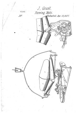
Joseph Grant's Patent Drawing for a Winding Machine for Setting Up Hat Bodies

National Archives, Restored Patent Drawings (Record Group 241) · Full-size scan at the National Archives · Catalog record
Text on the drawing
Words on the drawing as machine-read by the National Archives; not checked. Useful mainly for searching.
42 / 1/2 / Winding muchine for selling use hat bodies. / 4734-4 / Patented April 10th 1827 / References. / .A Frome B bue c Supporter D Fin E Double stand F Profes har to Semicircular rod.- H. Short stud / Frustums of cones.. J Two cored A Two upright vitandarte of iron Is Florize tal iron shaft n Pulley / .V. Bevel wheel, 36 testh 0. Bevel wheel,42 tath. P Inclined tumbling shaft. ll standard supporting wheck / R iron standart de Pouble beach wheel the end of shart 2,36 teeth alus T Another double bevel / wheel. U. Mate with a shit V Stud w Bevel cog wheel 27 teeth V. short tumbling shaft. / Y. Bevel cag whee, 24 teath 2 Bevel oog wheel on the base of the cene a A bevel wheelonth / end of the horizontal shaft. b Honizontal bevel wheel, 42 teeth e Pinion wheel a Large / horizontal wheel, 100 teeth. e Handart supporting the upper end of shaft f. g.Flate / of iron, from its center pafees upowards the itud he , Rad with a regulating screw / li / to Sever which gives the vibrating motion.- / Regulator. / 4 Band / GE / Francis Senne delt
USPTO scan
The patent as scanned by the USPTO
-
 Page 1
-
 Page 2


U.S. Patent and Trademark Office · Google Patents
Published accounts: specification
Specification printed in the Mirror of the Patent Office (1828) with its plate


American Journal of Improvements in the Useful Arts, and Mirror of the Patent Office, vol. 1 (1828), printed p. 53 · View the page
Transcription
Machine-read text of the specification as printed in the Mirror; not proofread. Check the page scan for figures, reference letters and spelling.
ya MACHINE FOR SETTING UP HAT BODIES. ‘ie ~ a By Joseph Grant, of Providence, Rhode Island. See plate V. Br P Specification Be it known that I, Joseph Grant, of Provi- seul dence, in the county of Providence and state of Rhode Island, 5 hatter, formerly obtained a patent for an improved mode of setting Ta up hat bodies, dated the 11th day of August, 1821; which patent 4 was afterwards cancelled, owing to the defective specification, and RY a new one granted on the 28th of April, 1825, for a machine call- aD ed “‘Grant’s improved winding machine, for setting up hat bodies;” a which machine was described, in the schedule then delivered as. to the patent office, and there duly recorded; and also by a mo- “9 del and drawing, deposited in said office. Now the present ap- : plication for a patent, is not for the principle, or motions, or any .* of the parts specified and described in the abovementioned sche- sy dule, but for certain changes in the manner and means of produc- ie ing the same combination of the rotary, or revolving, and the ro vibrating, or traverse motions of the said machine; which altera- ia tions effect these purposes more equably, with greater certainty a and regularity, and the parts concerned are less liable to get out a of repair, than in the machine as constructed according to my former specification. To make the subject of the present patent quite clear and explicit, I shall first give the description of the machine, as it is in the specification of my former and corrected a patent—it is in the words following: 2 This improvement consists in a combination of motions, viz: a the rotary, or revolving motion, with the vibrating, or traverse a motion, which winds and forms two hat bodies, and crosses the _ wool from one extremity of the hat bodies to the other, at one | a operation, as follows: A frame, the front side of which forms — aa an obtuse angle, the opposite side forms the sixth part of a cir- a yee cle, the end of each secured by an upright, is placed in front of, ty and opposite to, the finishing doffer of a carding machine of the common construction, and connected with the carding machine, _ 7 by bands, as hereafter mentioned and described. ew This frame supports four frustums of cones, placed two by ‘ 3 two, forming an obtuse angle down, with their bases inward, supported with proper bearings at each end. ‘These four frustums of cones receive and support two cones, with their bases in contact, of proper size and shape to form the hat bodies. The whole is suspended by a semicircular rod, each a end of which is fixed in the frame, and traverses on a swivel in ae the centre of the arc of the semicircle, and secured above. The frame also rests and traverses on a pivot, under, and in the cen- 5 tre of two wheels, hereafter mentioned. The rotary, or revolv- a ing motion, is produced by a band from the carding machine, _ e. hes: SS a Sse oe Sop ey a.
Lhd gay spall A a 7 4 — Abst passing between and round the horizontal wheels alluded to beai which are in front of the frame. Another whirl, or pulley, aes? is fixed on the same shaft, and above one of the beforementioned two wheels, (immaterial which) round this pulley passes a band, to another whirl, near the centre of the rites above, and on ad me the same shaft of this last mentioned whirl, is a pinion wheel, Me which gears into a bevel wheel, that is secured to the baseof SS one of the front frustums of cones. This bevel wheel gears into another, secured to the base of the opposite frustum of a cone; this gives the rotary, or revolving motion, to the two cones on a which the hat bodies are formed. The vibrating, or traverse motion, is produced by a second band from the carding machine,, passing round a horizontal pulley; below this pulley, on the same shaft, is a pinion wheel, which gears into a large horizon- ; tal wheel, near the edge and onthe upper side of which, is a pivot, which passes through the end of alever. The other end of this lever is a pivot, which turns down and enters a brace, bed, and this brace having several holes at proper distances from each other, serves as the first regulator, and is confined in the front and under one side of the frame, opposite the large horizontal wheel last mentioned; this lever gives the vibrating, or traverse Bi motion to the frame.
The large horizontal wheel last mentioned, is so placed, that a A line drawn from its centre to the brace in the front, and under one EH side of the frame, forms a right angle with the brace, when the frame stands square with the carding machine. Under the last mentioned horizontal pulley, is a plate of iron, which receives ne lower end of the shaft of the pulley and pinion wheel. The re of iron also supports the stud on which the large horizontal inne Coleen turns. To this plate is attached a screw regulator, by which the large horizontal wheel is adjusted. ye, tee _ The wool is weighed out in a sufficient quantity for two hat bodies; and, after passing through the carding machine, is received aia by the two cones that form the hat bodies. By the combination of motions before mentioned, the cones are covered from end to __ end, the width of the web forming the tip and band of one hat boa ay, Ween crosses over and forms the hand and tip of the other hat body; and, at the same time, places a suitable thickness in the ue band and square, and thinner at the tip, crossing the wool in every part of the hat bodies. The before mentioned four frustums of aia cones serve not only to. put the two cones in motion, but also to press the wool to the cones. The hat bodies being thus formed, they are separated in the middle, or at the base of the cones, and me then slipped off—and so on with others. What | claim as my specific improvements, and for which a patent is now solicited, is the mode of erossing the wool by the traverse motion of the machine, and the revolution of the two eae ae . eee en ae sath SR ig cones which form the two hat bodies, entire, upon four or more . _ frustums of cones, at one operation: contradistinguished from the methods of Silas Mason, and others, who use three cones which Due have no traverse motion, and could only form one hat body (as 4 far as the inventor is acquainted) at one operation; not crossing the wool in forming the hat body; and moreover, leaving the ee one hat body, which it does form. imperfect, by being perforated through the crown or tip by the arcs of the cone on which it is ei formed.” ;
now proceed to describe the same machine as it is constructed with those improvements, for which the present patent is ag claimed, and omitting those parts which are unnecessary in the ee new arrangement, i, The frame on which the machine stands, is of two inch plank, na one piece of which is ten inches wide, and extends from the : front to the back; about three feet in length, more or less; at sit the back end is a cross piece of the same plank, thirteen inches Res wide, or thereabouts, and two feet six inches long, more or less, ie halved on to the first described piece, and forming together a a figure resembling the letter T. Near the front end of the frame just described, is an iron cup, sunk in, to receive the lower end of the supporter, which is formed into a pivot, to stand on and work therein. This supporter is a strong shaft or bar of iron, 4 rising from the pivot just mentioned, not perpendicularly, but ES curved outwards sufliciently to admit the position and action of the cog-wheels to be hereafter described; it then turns inwards : and still ascends obliquely, until it reaches the proper height at s which to give bearings, to the lower ends of the four frustums of Ss cones, which are described in my former specification; and here. . the supporter is so bentas to sustain them all in their proper position and relation to each other. iif On the upper part of the supporter, and perpendicular to the ee pivet on which it works, at bottom, is a pin passing through a ole in a strap or band of iron, or double stand, which passes. a down on each side in front, and is securely fixed at bottom, by a bolts and nuts, to the frame; this pin, with the pivot below, form a the axis of the supporter, and allow it, and the frustums of cones “a supported by it, to traverse from right to left, and vice versa. 4 A cross bar of iron extends along the middle of the machine; at right angles with the supporter, to which it is attached at its ef centre from beneath, by a screw bolt and nut; this bar inclines 3 gently upwards from its centre, towards each end, at which end 3 it turns up vertically, and terminates in hooks, by which it is sus- ": pended by a semicircular rod, which supports the whole. Near to each extremity of the cross bar, is a short stud, attached : thereto by a screw bolt and nut, which bolt passes through a hole in the cross bar, and a slit in the stud, so that said stud gan be raised or depressed at pleasure; the upper end of each of om these studs is formed into a fork, at the extremity of each prong of which is a hole, and these holes are the bearings for the arcs) of the outer ends of the four frustums of cones, before described; a as the studs are elevated or depressed, soa greater or less inclination inwards is given to the frustums of cones. Upon these frustums of cones, lie the two cones with their bases in contact, as described before, on which the hat bodies are formed. On the cross piece of the frame before described, at the back part i” of the machine, and at a suitable distance from each other, are two upright standards of iron, twelve inches more or less high, and having their lower ends formed into a flat plate, with a slit oy therein, through which they are fastened by a screw bolt and ‘i nut, to the frame beneath; by this mode they are capable of any adjustment which occasional alterations of the machinery ey may a pe As these standards are to receive the horizontal e iron shaft, which I shall next describe, the upper ends of them, ‘ig me are to have open slits or bearings, in which that shaft is to lie and revolve freely: but the standard which is nearest to the pulley that connects the shaft with the carding machine, must be ~ 4 bent inward towards the front of the machine, at the top, and ot the shaft secured in the slits of this and the other standard, by pins passing through them.
The horizontal iron shaft is about two feet long, more or less, “oe and about one inch in diameter; it revolves in the standard just 4 described, and has on it at one end a pulley ten inches diame- a ter, more or less; over and round which passes ‘a band from the 9 Zz carding machine, and gives motion to the horizontal shaft, and Me thereby to my whole machine. About eighteen inches, more or less, from this pulley, on the same shaft, is a cast iron bevel ae Pe ~ wheel, having thirty-six teeth, which mash into the teeth of an- : By E's other cast iron bevel wheel, having forty-two teeth, which wheel igattached to a long, inclined, tumbling shaft, about three-fourths of if, a an inch in diameter, supported by an iron standard from the frame , beneath, exactly similar to the standard of the horizontal shaft; this inclined shaft goes forward to the front of the frame, about two feet nine inches in length, and rests m a short iron standard there, in both which standards this shaft freely revolves; on the “a end of said shaft next the front, is fixed a double bevel cast iron cog wheel, having thirty-six teeth, mashing into another double bevel cog-wheel at its side, corresponding in all respects with : the other, but the axis of which is a stud, permanently fixed by a means of a plate at right angles to the outside of the supporter. F This plate has a slit through which a screw bolt passes into the supporter; and is secured by a nut: which slit allows the last mentioned double bevel wheel to be adjusted so as always accussi rately to gear into its fellow; these two last mentioned wheels it be a ee, eS a See Pe eee a cay on Sy Nt a ant iy oe oa i ay 7 44 ‘ i oe: Pe Be k ie x ; ee Sia.
a soca bevelled, that as the machine traverses from right to ; ae ia eg vice versa, the cogs | on each side of each wheel, may ae alternately, into those of the corresponding wheel..| The Baas double bevel cog wheel which has the stud for its axisj;mashes into a single bevel cog wheel, having twenty-seven teeth, and fixed cid upon a short tumbling shaft, three-fourths of an inch in diameter, ret the arbor of which, works ina plate, fixed to the inside of thesup> porter, by a screw bolt and nut: this tumbling shaft, inclines upwards, until it reaches the supporter just under the axis of ‘the ie two front frustums of cones; in which place, its upper arbor is secured by a plate of iron, fixed with a screw through anadjusting slide, to the under side of the supporter. On the upper-end of a this tumbling shaft, is a small bevel cog wheel, having twenty-four aa teeth, which mash into the teeth of the bevel wheel which as se- a cured to the base of one of the front. frustums of cones, and this. oan bevel wheel, goes into another similar one, secured.to the base of the opposite frustum of a cone, and gives the rotary or revolving wag ipesion to the two cones, as has been already described in my . ormer specification. : 96 ass At seven inches from the bevel wheel on the first describ- oe ‘ed horizontal shaft, and at the termination of said shaft, is ee another bevel cog wheel, having thirty-six teeth, mashing, on the ge: lower side of said wheel, into the cogs of a horizontal bevel eae wheel, having forty-two teeth, which is fixed on the upper end Sw of an upright shaft: On the bottom of this shaft, is a pinion wheel, age a of from ten to sixteen leaves, according to the desired size of the Bs hat bodies, which gears into a large horizontal wheel, which ree has one hundred teeth. The aforesaid upright shaft, hasabear- ‘ing in the frame below, having just passed through a plate of iron, presently to be described, and its spear end. is secured by an ory ty iron standard, having its lower end formed into a plate, with a slit, and fixed to the frame by a screw bolt,and nut, like the other _ wa ‘standards, and its top bent over, with a hole in the same to re- a ceive the upper axis of the said upright shaft. The plate of iron a through which, at one end, the lower part of the said upright shaft :. passes, is circular at its other extremity, and from its centre, arises a stud, on which the large horizontal wheel, haying one hun- a oe dred teeth, turns; this plate is attached to a rod, with a regulat- a ing screw, by which the position of the horizontal wheel is ad- ae Gjusted. On the surface of the large horizontal wheel, near the a ay edge, isa hole to receive the end of a lever, which gives the vi- ; __ prating or traverse motion to the machine—or the same object Be. may be effected by a pin, fixed on the upper side of the ag ‘wheel, and a hole in the end of the lever, to drop on the pin; the other end of this lever,-reaches to the front of the frame, on the Fe other side of the machine, from that on which is the large horizontal wheel, and is there attached to a piece of iron, which I lie JAS at a Theat a " oh gy EE ET pee noe wae a. et. hans TERY sie Sy Me =" a ae if ag ee ee AMEN ICAN OURN, Le } Pe ot Ae: cers! \ ed lied ai 4 Pris call the regulator, and which, by sliding on a sweep, under is tis rection of a screw, adjusts the traverse motion, to a larger or sii smaller distance, with much greater exactness than could be done by the holes in the brace, as described in the foregoing specifi- Be’ cation. Thanks __ The sweep is a bar of iron, firmly attached, at one end, to the bottom of the supporter, and curved, at the inner end, to allow it : to pass by the iron strap or stand before described, when the machine is in operation.
What I claim, as a new and useful improvement, in the afore- 4 gaid machinery, consists of the iron supporter, the cross bar, the double and single bevel cog wheels, the iron shafts, the positions, . and combination of these with proper bearers, standards, and ene’ slides, the sweep, and regulating slide, all of iron, or other metal, superceding the wooden frame, pulleys, and bands, and the brace a with holes, as was described in the specification of my former . patent, above referred to: the present described arrangement, _ Way _ producing the combined rotary and traverse motion with great-e = __ hp a, regularity, certainty and durability, than in the former ae In testimony that the above is a true specification of my said “as enibegerne as above described, I have hereunto set my hand seal, this 22d day of March, in the year of our Lord one thousand eight hundred and twenty-seven.
fe JOSEPH GRANT.
JAMES SHAW, : .
Be WM. H. asi WERE: Pit 9 og _ Date of the patent, April 10, 1827: i ae ,
[References to the plate, as printed:]
ee 4 a Z A Hag! ie ie Nors.—We are already sensible that some errors and omissions will have — a
Published accounts: journal notice
Notice in the monthly list of patents
Journal of the Franklin Institute, vol. 5 (1828), p. 64 · View the page
In the machine for setting up hat bodies; Joseph Grant, Providence, R. I. April 10.
About this record
- Patentee
- the Journal of the Franklin Institute, Journal
- Date
- the Name and Date index of patents, USPTO records, Jim Shaw's X-patent list
- Invention
- the Name and Date index of patents
- Listed in
- the Name and Date index of patents, USPTO records, Jim Shaw's X-patent list, the Journal of the Franklin Institute, the Mirror of the Patent Office (1828), S. A. Elliot's printed list of patents, Burke's List of Patents (1847)
- A drawing was printed in the Mirror of the Patent Office (1828).
- The patentee's full name comes from the Franklin Institute's journal.
- The specification was printed in the Mirror of the Patent Office (1828).
- S. A. Elliot's printed list of patents gives the same name and date.
- in_burke