

Drawings and documents
National Archives restored drawings: drawing
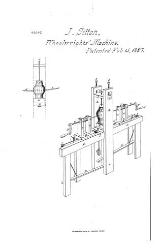
J. Sitton's Patent Drawing for a Wheel-Wright's Assistant

National Archives, Restored Patent Drawings (Record Group 241) · Full-size scan at the National Archives · Catalog record
Text on the drawing
Words on the drawing as machine-read by the National Archives; not checked. Useful mainly for searching.
144. WOOD WORKING. / 3. SPECIAL WORK MACHINERY. / WHEELWRIGHT / rol. b page. 319- / [31] Wheelwright Mach's / Boring Hubs. / #150 / Patented 15 Feb 152% / on / 4664-7 / J. SINTON / DIVIGION. / Minde-rrights assistants / A. / B Bench / C. Capa a ton piece Screns to D / M. / D. Fraze / E Boring. Mach: e.e / F. Cylinder / a Augers / H. Canza / I. Pullies.i weight / K. Treadles / T. Small topplate of Iron . / M. Blocks / N. Bottom place of Iron marked for spokes / D. Screw / P HILTH / Patent Office Nov 2.1540 / Made under the direction of the Commissioner of / natents in confermaty with act of 3"arch 1537 / nieconoth / Shichland Del / of nations
USPTO scan
The patent as scanned by the USPTO
-
 Page 1
-
 Page 2


U.S. Patent and Trademark Office · Google Patents
Published accounts: specification
Specification printed in the Mirror of the Patent Office (1828) with its plate

American Journal of Improvements in the Useful Arts, and Mirror of the Patent Office, vol. 1 (1828), printed p. 177 · View the page
Transcription
Machine-read text of the specification as printed in the Mirror; not proofread. Check the page scan for figures, reference letters and spelling.
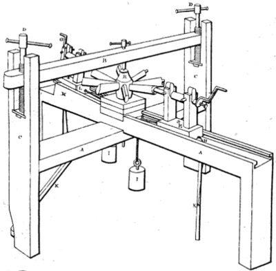
By John Sitton, of Pendleton, South Carolina.—See plate XVIII. figs. 2, &c. : eee: Specification.—A frame, like a common wheel gallows, as it ‘a is commonly called, made of timbers three by twelve inches; <a the first horizontal piece or bench, two feet ten inches from the _ Pia floor, the cap or top piece about two feet from the topofthe = other; this cap is put into the top of the two upright posts,and instead of the common key-wedge at one end, it is fastened at each er . end with screws of wood or iron perpendicularly, so as to raise aa” the cap or lower it to confine the hub. Another frame of the same sized timbers, three feet high, is put across at right angles with the other, and let strongly together; this frame may be ees made of any size; one of the angles or benches to extend eigh- a teen inches further than the other three, on which the carriage of See the boring machine runs. This machine is made twelve inches — awe Jong, the bottom one and a half inch thick, six inches wide, into ae which is mortised two perpendicular posts, one and a half by eae three inches, ten in hes high, six inches between. _ In the top of x so these is fixed a cylinder, through which the shank of the auger passes; on the end of the shank is fixed, by ascrew, acrankto turn it by hand, the cylinder is confined down by a concave key oneach end, and a pin through each of the upright posts totighten <a it. Six inches from the centre of the gallows, or frame, is a pulley, 2a and one near the extremity, or at any given distance, over which accord passes each way from the centre of this sliding carriage, ST to which it is fastened by boring two holes and running the cord. oe through, and putting a knot on the upper side of the bottom of 8, the carriage to command it each way; one endof the cordis then fastened to a weight of about twenty-five pounds; after per ak: runing over the centre pulley, this weight moves the auger ese es. against the wood. The other end of the cord passing the rear a pulley, is fastened to a tight bar or treadle of wood, one end of te which is fastened by a pin or screw to the side of one of the a a high perpendicular posts, which extends eighteen inches past =. where the cord is fastened to it, (perpendicularly under the bo pulley,) this bar is raised by the weight as the auger proceeds, ao a and when bored, to stop by putting the foot on it, is run back to 1 commence another hole. Guides are put on the bench and on the carriage to make it bore exactly straight, and a groove or. a rabbit under the bottom of the carriage inorder to give room for the cord and pulleys. . Riu yo To give the dish of the wheel, another carriage of the same ie description is placed on the other end of the same horizontal <a piece.or bench, on which is ga inclined just as much down asmay be desired, with the same weight, &c. and at the same a ee ey a yn ea ae a Mia ny Te a “F OR eek OP ae ee ee Pe Sy MMMM cA A , he te time one is boring the hole for the inside of the mortise in th wn : le ‘nave or hub, another bores the outside; whem the nave is ready ie for boring, a small peg or plate of iron is put on the small end, Hae with two small nails or tacks in it to keep it steady. Square blocks are:put on the centre of the frame then to raise the hub He or nave a proper height;, on the upper block, on which the nave v3, rests, is a plate of sheet iron, with marks for the number of Re spokes. intended; the nave is put on it, the large end down, rae and confined by a screw through the cap against the plate on the upperend of the hub or nave, near the lower end a small tack is put in as a guide to move. by in boring; there is a pin el passing through the bench, the blocks, and up in the centre of the nave, which is the pivot it turns on. T'wo hands will bore all age the holes in a hub in four minutes. A patent auger will bore at _ the rate of twenty-six inches in a minute; but any kind of. an auger will bore with ease and exactness.
bi To bore the felloes to receive the spokes, a box or frame is bie tyr made a proper height to bring the centre of the felloe to a level a with the auger. On this frame-a rest is put, through which the auger passes; a couple of pins are put on the inside of this rest, against which the felloes are put, so that they may be bored exactly from the centre, the faced side of the felloes to be put we - down, the screw from fhe top confines them for the auger; benad tween the guide for the felloe and the auger a hole is made in ce the box, through which the chips drop from the auger. ‘ia To bore the holes for dowelling, a couple of pin holes are made in the guide, through which the auger passes, one equiae distant from the auger on each side. When one end is bored, we by changing the pin to the other side, and keeping the faced a side of the felloes down, the holes will exactly fit. To cut the tenons and shoulders on the spokes, the wheel is yt. put into the frame, and fastened, as for boring the nave. The me tenon or hollow auger is put into the carriage; this auger or : ee instrument is made hollow all the way, three or four inches next met ye the bit is bored out the exact size the tenon is to be made; on this end is a piece of cast steel brazed, swelled a little, the bit ae cut on the end, and the swelled part fluted out with a round file, Bar similar to a screw auger, only small and many indented places oe , to let the chips drop, to guide the auger and hold the spoke, a ie’? , rod of iron passes through the same all the way; a button is se made to fit the inside of the auger, the point of the rod extending ba far enough through to hold the wood; on the other end is a nut screwed or riveted on, so that when the auger is ready to start, by a tap on the nut with a hammer, it is driven up to the crank, and the button on the front to the bit, and the point in the spoke; the point holds the wood, the button guides the auger, the Ee - spokes are all shouldered and tenoned to a gauge, and equal on ag hoth sides. : rg seg a i By Oo ae 5) See, ae teh ig aie =o ia ig gil Me aS eat RE MM a, Wi ere ee ay “The same blocks may be ies to raise the wheel to cutthe spokes which are used in boring the nave. To cut the tenons, ei the pulley is moved back to a proper distance on the bench; is the auger starts at the end of the spoke to cut the tenon, at a Bs proper distance a stop is placed, which forms the circleofthe wheel. This machine will lay off and bore the nave, lay off and bore the felloe, cut the tenon and shoulder on the spoke = Be complete, and more exact than can be done by rule; the spokes being shouldered on both sides are stronger. " ee With this machine a good hand can with ease make a wheel Complete in five and a half hours after the nave or hub is turned, ae ha the spokes split out, and the felloes Sawed. “ Re Every improvement herein described, invented, made and used_ Bis by me in my shop at Pendleton, South Carolina. Ist dayof November, Anno Domini, 1826. 1G Saea Ati Ki JOHN SITTON. ee __ Date of the patent, February 15, 1827. eo
[References to the plate, as printed:]
REFERENCES.—PLATE XvItl. figs. 2, &c. Te A The horizontal supporting bench or wheel-gallows. SNe: Berra (3 B. The cap. . . : : wi ye hg Se ASS The two upright posts. mit of he hae ae My D_ The screws working in a permanent iron collar below. ~ py #, ay et Carriage of the horizontal boring machine. — + Sa The auger for boring mortises in the hub. of SS ates Thecrank to do. : “ae
Published accounts: journal notice
Notice in the monthly list of patents
Journal of the Franklin Institute, vol. 5 (1828), p. 62 · View the page
In making wheels for carriages, being a machine called the wheelwright's assistant; John Sitton, Pendleton, S. C. Feb. 15.
DATAMP: illustration
Illustrations from DATAMP

DATAMP (Directory of American Tool and Machinery Patents), via the Internet Archive · Archived DATAMP page
About this record
- Patentee
- DATAMP
- Date
- the Name and Date index of patents, DATAMP, USPTO records
- Invention
- DATAMP
- Listed in
- the Name and Date index of patents, DATAMP, USPTO records, Jim Shaw's X-patent list, the Journal of the Franklin Institute, the Mirror of the Patent Office (1828), Burke's List of Patents (1847)
- A drawing was printed in the Mirror of the Patent Office (1828).
- The specification was printed in the Mirror of the Patent Office (1828).
- in_burke