

Drawings and documents
National Archives restored drawings: drawing
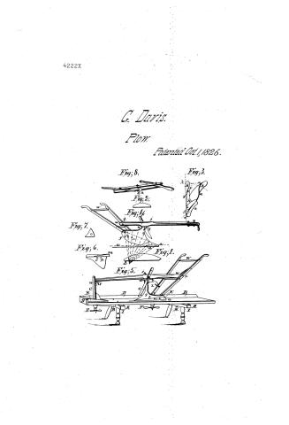
Gidion Davis' Patent Drawing for Improvements in the Plough, Double and Single Plough Trees, and Plough Bench

National Archives, Restored Patent Drawings (Record Group 241) · Full-size scan at the National Archives · Catalog record
Text on the drawing
Words on the drawing as machine-read by the National Archives; not checked. Useful mainly for searching.
Finlered / Mr2 / 97. PLOWS. / [114] Plows. / Voe4 1817to1822 / CLASSIFICATION / 4'2224 / DIVISION / Derrie / Improvements. in the Plough Double and single trees and Plough Bench / Patented October 1 1825 / 0.9 / Her this patient see / page 129. Vol4. 18tyto1122 / Fig.6 / Ro / Fig.3 / socks / Fc / E, / Fig. 9 / Augh / for Item peta / 13 See claringfor line a ate
USPTO scan
The patent as scanned by the USPTO
-
 Page 1
-
 Page 2


U.S. Patent and Trademark Office · Google Patents
Published accounts: specification
Specification printed in the Mirror of the Patent Office (1828) with its plate


American Journal of Improvements in the Useful Arts, and Mirror of the Patent Office, vol. 1 (1828), printed p. 134 · View the page
Transcription
Machine-read text of the specification as printed in the Mirror; not proofread. Check the page scan for figures, reference letters and spelling.
i _ IMPROVEMENTS IN THE BARSHARE AND FALLOW PLOUGH. By Gideon Davis, of Georgetown, District of Columbia. ' . The great disideratum to be attained in the barshare or fallow plough, 1s that it be so shaped and construcied, as to detach the furrow-slice trom the solid ground, raise it up and turn it over, in the neatest and most uniform and effectual manner, with the least possible labor, both to the pioughman and the team; combining at the same time, the advantages of being simple in its structure, strong and durable, easy to keep in repair, and cheap. The mode of using, it is desirable should be such, as will cause the least trouble and inconvenience to the ploughman. With a view to combine, as far as it is practicable, these various objects, I begin by making the mould-board, landside, and standard, (or width for the beam to rest on) all of cast iron, and in a solid piece: this is done in the manner in which Charles Newbold, of New-Jersey, made his improved plough, patented in the year 1797; but with the several alterations and improyements, hereinafier particularly specified. First—Of the shape of the moulding part, or what is commonly called the face of the mould-board, the general principle, heretofore concurred in, by all scientific men, who have turned their attention to this subject is, that as the furrow-slice is detached FY from the solid ground, at a straight line, parallel to the strface, ly at such depth as may be required, that it should be raised up and ) turned over, so as to retain, as far as possible, the same ttat 7 shape. Inorder to accommodate the face of the mould-board, ail to this idea of raising the furrow-slice up, and turning it over, it a ar has been so constructed, as to form straight lines lengthwise, either horizontal, or a little inclined, and also to correspond 3" with another set of straight lines, at right angles with the landside, or nearly so, commencing at the point, touching the edge P of the share, and lower edge of the mould board. These last mentioned straight lines, as they recede from the point of commencement, gradually change from a horizontal to a perpendicular direction, and even pass beyond the perpendicular, so far, as to give the proper overjet behind. It has been thought, that mouldboards so constructed, would fit and embrace every part of the furrow-slice, in the operation of turning it over; not observing that the furrow-slice must, necessarily acquire a convex form, on : ____ the underside, during the operation, by which it is raised up _._ and turned over. .
The truth is, however, that in raising and turning over the Bt furrow-slice, it always either acquires a convex form on the un- Be is'y. derside, or else it is broken off into pieces, and thrown over; as Oy aaa “might, therefore, be anticipated, it will be found, that all those 4 mould-boards, which are constructed on this principle, wear _ through, in the operation. of ploughing, about midway; whilst ia an i To fl ee meson as ee the upper and lower edges are scarcely rubbed. | It also necessarily results, that ploughs of this construction, work hard, and aa are of heavy draught, because the mould-board, not being adapted Ban) ‘to the convex form, which the furrow-slice is disposed to assume, es lifts the furrow-slice at a single point, and that in the middle, “a instead of being equally applied throughout the entire ies ee In order to meet, and remedy the inconveniences arising from this form of structure: I form my mould-board into a different .. shape, and instead of working the moulding part, or face of the By mould-board, to straight lines; my improvement is, to work it ‘S to circular or sphere lines. By repeated experiments, I have asines era, that in one direction, viz: from a (fig. 4) inclining to back part, the circle, or segment of the mould-board, to “3 which the mould-board is wrought, should have about three aa times the radius of the smaller segments, represented by the ee lines lettered c, &c. the former being about 36 inches, the lata ter 12, in order then to shape the moulding part, or the face of athe mould-board, having obtained a suitable block, I begin, by ~ “3 Jaying off the bottom, (fig. 3) and (fig. 4) by circular or spheric Mines, ataaa. If I intend to construct a plough of a proper Size, to cut and turn a twelve inch furrow, I strike this segment ; a circle of thirty-six inches radius, (fig. 1) and at twenty-four ; Henches back, from the point to C, at right angles with the and-side, and twelve inches from the landside; this circle, will j--Mtersect the angle line; this circle is extended out from the landsside; then I work the block to fit the same segment, inclined ftom a (fig. 4) at the point of the share, toa, ata perpendicuy lar raised twelve inches from the horizon, with the circleexs tasended in towards the land-side; then having wrought to the YS ae hape of these two lines, I apply the circular part of the smaller je a segment, (fig. 2) and work the face of the mould-board, until What segment, will have an equal bearing on all parts, corres~ a ponding with the cross lines c c c, &c. which, if produced, — ia would all terminate at a point at d, which is about thirty-six inches from the perpendicular, where the line a a crosses the linc S 4b; this being thus worked off uniformly, forms a section of a, and oxodromic, or spiral curve; and when applied to practice, | “a is found to fit, or embrace every part of the furrow-slice, far 4 more than any other shaped plough. The plough may be made a larger or smaller, suited to deep or shallow ploughing, by ens larging or diminishing the radii of the segments which it ig Wrought by. Believing that this mode of shaping the moulding P=att or face of the mould-board, is an original invention of my Tah Ofwn, not heretofore used or known, and that it isa most im- a Prtant improvement, in the shape of the plough, I claim ie 2 eamclusive privilege of making, using, and vending the same, at . et “a ee ee ae << es 2, ies ey, i SSS aS Ee Second.—Shape of the throat and hind part of the mouldboard. : ee :
ay The shape of the throat is exhibited in the accompanying drawing, fig. 4, fig. 5, (2). I construct this part of my plough, with a gentle curve from the top of the share, entirely up to the beam, which at a suitable height, for a plough designed to turn a a furrow-slice of twelve inches in width, say about sixteen inches, will incline forward as if comes up to the beam, to form a birth for it to rest upon, inan easy circular form, I dress it off also round, as it ascends from the share, making it broader and 4 broader as it approaches the beam. The object of this peculiar : shape is, to prevent brambles, long grass, &c. from lapping sO short as they would do if the front of the throat were sharp, and the inclination forward at the upper part of the throat formsa curve with the under side of the beam, so as to prevent any yy thing in ploughing, from being jammed under the beam; the presa sure below naturally forces the incumbrance up, and forward, when it faces over, and the plough cleans itself. This I consi- Ie der an improvement of peculiar value in ploughing in clover, long manure and the like.
a The hind part of the mould board, fig. 3 and 4, f, I dress off in a gentle curve from the end or wing of the share up to the hind corner of the mould board. This shape | have ascertained to’an- 2. swer every purpose in-turning over the furrow-slice, and asit does not come down to the bottom of the furrow, the plough iw works with much less friction, is lighter, cheaper and handsomer. Believing these shapes for the throat or breast, and the hind part of the mould-board, not to have been known or practised before et? my application of it, and that they constitute valuable improve- Ay ments in the construction of the plough, I claim the exclusive a right to use and dispose of them.
Third.—The structure of the land-side with the mould-board and standard, or the fore and top part of the mould board. Charles Newbold, made his mould-board, land-side, and 4 standard ef one piece, and of cast iron. In connecting his landside to the mould-board, he made it nearly square and stout, in order to give it strength. I make my land-side thin and broad, q 9, fig. 5, which gives more strength, vertically, without so much Ba hie weight. This form, also, makes it a guard, which prevents ; __ sods and dirt from working in, and clogging that part of the _. plough. In order then to give additional strength tothe land-side Sidewise, and to connect it at a proper angle with the mouldte board, I makea rib, h, fig. 3, on the land-side, about midway ; ___ between the bottom and top, say about two inches and a half from the bottom. This rib is made broad where it joins the mould-board, at i, and tapers as it goes back tothe birth for the _ handle to fasten on, where it terminates at , fig. 3, where J Fe ee Saale oa re ee ed vi ib Bieri hg po. " en; ayes A ‘ BE Ese. crate ty wake a projection or jog, which cannot be represented in the a drawing, to raise about half an inch, for the end of the handle to A rest against. This rest, or jog, sustains the pressure of the handle tin.,! endwise, so that the screw-bolt, is only required to confine it to a the side. C. Newbold made the standard of his plough to pass P ‘up through a mortise in the beam; in mine, it extends only up to the beam; the beam is fastened on to it, witha strong iron screw a bolt, which may be made either to pass up through the top of the standard in the front part of it, and through the beam verti- Ty cally, j, fig. 5, or to pass through the beam, in an inclined divection; and containing the same inclination through the oe of ; the standard, having on the inside a birth for the nut to work on, ee J, fig 4. There are ploughs in which the beam is fastened on the top of the standard, with two bolts. The improvement which I claim to have invented, consists, therefore, only in these. particular modes of connexion. The advantage of it consists in this, that the fastening being made by a single bolt, upon which. Res the beam can turn, it enables me to adjust the landing of the a plough, by a simple operation in altering the position of the end Se of the beam, where it is united to the handle. This will be more ~ Re particularly described, when I speak of the stocking of the on gplough. ne There have also been landsides heretofore constructed which yevere made thin and broad, but supported in a different manner; tmny improvement, therefore, consists only in the mode of making tihe rib, the projection or jog in the inside of the landside, the form omf the top of the standard or the fore and top part of the mould = ‘Soak board, which being made to extend forward under the beam, Se e -qualises the bearing of the beam. Thus a smaller piece of wood : woe will be more sufficient to form the beam, than if the fastenings . the handle and standard are brought nearer to each other. Sey Fourth—The Shoe.
Charles Newbold made a bar of wrought iron, which he caused to extend back from the share to the end of the landside, below and fastened to it with a screw bolt passing up through both 3 the shoe and the landside. ee Stephens, of New-York, applied his shoe on the bottom of the. ; landside of his plough and fastened it on by extending an ear or projection*up on the inside of the landside, to which it was fastened with a small screw-bolt passing through both; shoes nstructed in this manner will only answer the purpose of pro- aah teting the bottom of the landside. “The side, however, is equal- _ ig So ly exposed, and in time will wear entirely off. To obviate this In<onvenience, I make a groove or countersink in the side and lowver edge of the landside of my plough, which forms a __ . 3 bisth for the shoe, and admits of the thickness without any ins Convenience a its projecting out, R, R, figs. 3, 5; the shoe exea a | ie tends round under the bottom of the landside, and fastenson whee or more small screw bults. ‘ ae a The improvement consists in so constructing and applying the shoe, that it protects both the side and bottom of the landside; it may be made of wrought or cast iron or of steel. roe me .? Fith—_New mode of making, applying and using the share of the plough, whether formed of wrought or cast iron. If l apply the wrought iron share, I make it in the usual way 4 by welding the wing on the landside, see fig. 6. But I make the bar or Gated to extend back of the wing, about twoor three inches, m fig. 6. and fasten it in the cast iron part of the landside with a small screw bolt, n fig. 5. ThenI fasten it to the mouldboard by means of a projection made on the front and lower part of the mould-board with an inclination forward, forming a dove= __ tail or hook which I extend through the share, see O, fig. 6. This mode will hold on the share very firmly, but as it isliable, being __ pale of cast iron, to break off, in order to obviate this danger; ia I fasten the share to the mould-board with a strong screw bolt, oi aving the head made to fit, a tapering hole made in the mould Ee joard, and passing down through the wing of the share, p, fig. 6, ee drawn Be tight with a screw nut. Ifit bea right handed plough, is should be a left handed screw, and if a left handed plough, then a right handed screw. This is somewhat the manner in ts which David Peacock, of N. J. fastened the share on his plough, ae patented in the year 1807, but with this difference, he put two
[References to the plate, as printed:]
screw bolts and a false coulter through the wing of his share, there= fore, made it stationary and without its being made fast to the cast __ iron part of the landside at all. But in my mode of fastening the a share on, by putting a piece of wood or leather between the wrought and cast iron landsides at n, fig. 5, the point of the share may be somewhat adjusted, and the bar always regulated to suit the shoe of the plough. The point and edge of the share is likewise of a different shape from any that have heretofore been Be made to my knowledge. Having remarked that the point of the share is always disposed to wear round, I make the point round gs at first. Ialso make it about twice as broad as usual, and of a course much thinner. The edge of the share is likewise made rather concave or hallow, this, being the shape to-which it naturally. wears. In consequence of this they wear much more uniformly, will last longer, and be less expensive. ie It is also a fact, that the broad round share or coulter point will enter and strike into the ground much better than those of the ordinary construction, and being made much thinner will retain Be aon Lod edge and work much longer without requiring repair. __ , Ih using the wrought iron share, the point or for and lower 2p ed the mould-board, especially if the point of the share is eae > lered to wear off very short, is liable to wear away. ‘Toob- ; oe Sar Fee ce Seek oe ete de a wed : Zi eo, ee nittexicht ee
Published accounts: journal notice
Notice in the monthly list of patents
Journal of the Franklin Institute, new ser., vol. 12 (1833), p. 170 · View the page
8. For an improvement in the Bar Share or Fallow Plough; Gideon Davis, Georgetown, District of Columbia. First patented October 1st, 1825.
About this record
- Patentee
- DATAMP
- Date
- the Name and Date index of patents, DATAMP, USPTO records
- Invention
- DATAMP
- Listed in
- the Name and Date index of patents, DATAMP, USPTO records, Jim Shaw's X-patent list, the Journal of the Franklin Institute, the Mirror of the Patent Office (1828), S. A. Elliot's printed list of patents, Burke's List of Patents (1847)
- A drawing was printed in the Mirror of the Patent Office (1828).
- The specification was printed in the Mirror of the Patent Office (1828).
- S. A. Elliot's printed list of patents gives the same name and date.
- in_burke