

Drawings and documents
Published accounts: specification
Specification printed in the Mirror of the Patent Office (1828) with its plate

American Journal of Improvements in the Useful Arts, and Mirror of the Patent Office, vol. 1 (Washington, 1828) · View the page
Transcription
Machine-read text of the specification as printed in the Mirror; not proofread.
IMPROVEMENT IN MANUFACTURING SHINGLES, By Willard Earl, of Royalston, Worcester county, Massachusetts. See Plate XXXIV.
Said improvement consists in such new arrangements and change of parts of my former machine for the like purpose, for which letters patent were granted to me by the President of the United States, bearing date September 3d, 1813, as to admit ee the use and application in said machine, of the circular saw instead of the perpendicular saw heretofore used; and the substitution of such other parts as are rendered necessary, by these a alterations, in order to effect the required timing, and proper movements of the respective parts thus altered, in connection Be with other parts of said machine.
In my former machine, above mentioned, ‘he progress of the ; A ai carriage and shingle block, by means of the rag wheel and dog 4 hand, was irregular and would be inconvenient with the use the circular saw, I. have, therefore, in order to have a ae regular motion of said carriage and block, substituted acog wheel ‘Sg and pinion, which acquire motion from the saw. shaft by means Be of a band and pulley around said shaft, as may be seen and better understood by reference to the drawings hereunto annexed. Instead of the crank and pit staff, to give motion to the saw, as ae inmy said former machine, I now use the drum wheel in common a form, and belt or band for the said purpose. I now move the ise carriage forward by means of a pinion ted upon one end of the We ? oul Sees cog Wiheel arbor, which extends under one side oie carriage he frame, and there is connected with a line of leaves or cogs, secured upon the under side of said frame. Said carriage is drawn : back to its first position by means of weights upon the. like prin- . ciples as in my former machine. The head block is.alsomoved —_ forward towards the saw by a weight fastened toa cord which , og is directed by small pulleys or sheaves, and passes round the. shaft or arbor of a fly, by which its otherwise too sudden de- —~ 4 scent is regulated, as will better appear from the the drawings See letter N, in fig. 1. : 7 ae In order that my said addition and improvements, combined with other parts of my said shingle mill, patented as aforesaid, a may more distinctly. appear, I have distinguished them in the drawings hereunto annexed, by letters of reference—while the. several parts, not thus distinguished, are what I consider, to be. 4 the parts of my said former shingle mill; yet, inorder to anam- 2 ple and clear exhibition of my manner of combining and apply- ee ing my said additions and improvements with said other parts of : said former mill, I deem it expedient and necessary to make drawings of the entire improved mill, in its improved or com- oo bined form.
The drawing fig. 1, is a plan of said improved mill, the drawing fig 2, is a side elevation of it. A, in each, represents the circular saw. B, represents the pulley fixed upon the saw ki shafts, which, connected with the drum wheel by means of the a belt or band, communicates motion to every part. C, 1s the cog wheel fixed upon one end of the arbor, which, at the other end, <a by means of a pinion, moves the carriage forward, and which ae is also comected and moved by pinion D. E, represents the saw shaft, having upon its outer end a pulley with grooves for the band of different sizes, by means of which, the speedof the . mill may be increased or retarded. F, represents the coveror ~ — 4 cap, which covers the friction wheel upon which the gudgeon 7 or neck of the saw shaft rests and turns, to keep out the dirt. G, is a ridge or elevation upon the cap, of sufficient height to a prevent the shingles, as they fall from the block, from falling up- ose onthe shaft. H, represents the space or passage way forthe 4 shingles—every one of which is pushed off endwise by the ~ ae succeeding shingle. I, describes the face upon its arbor N, Mi which governs the motion, in some measure, of the weight con- __- a nected with the head block. K, describes a small wheel or tru ek, with grooves fixed upon the arm of a perpendicular standard pas- are sing through a mortise in the outside of the frame of the mill, aa with which to regulate the band as occasion may require, and ale which I call the tightener. L, shews the pulley with grooves ... of different sizes fixed upon the arbor, at the other end of which Sy is pinion D, to which cog wheel C, is connected. M, represents mc s ! ie Da et A ee ha oe beds ee, eee. AZ sie! , . ae 7 342 j AMERIGAN JOURNAL, the cord oahiave, that draw the head block forward to its place. N, is the fly arbor with the cord around it, and O, is the shaft or arbor of the cog wheel, and of the pinion which gives motion to the carriage while the machinery is performing the opj . eration of making the shingle. megs | Fem _ Date of'the Patent, December 28, 1822. ibs “ae “5
DATAMP: illustration
Illustrations from DATAMP
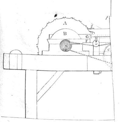
DATAMP (Directory of American Tool and Machinery Patents), via the Internet Archive · Archived DATAMP page
About this record
- Patentee
- DATAMP
- Date
- the Name and Date index of patents, DATAMP
- Invention
- DATAMP
- Listed in
- the Name and Date index of patents, DATAMP, Jim Shaw's X-patent list, S. A. Elliot's printed list of patents, Burke's List of Patents (1847), the Mirror of the Patent Office (1828)
- S. A. Elliot's printed list of patents gives the same name and date.
- in_burke
- The specification was printed in the Mirror of the Patent Office (1828).
- A drawing was printed in the Mirror of the Patent Office (1828).