

Drawings and documents
Published accounts: specification
Specification printed in the Mirror of the Patent Office (1828) with its plate
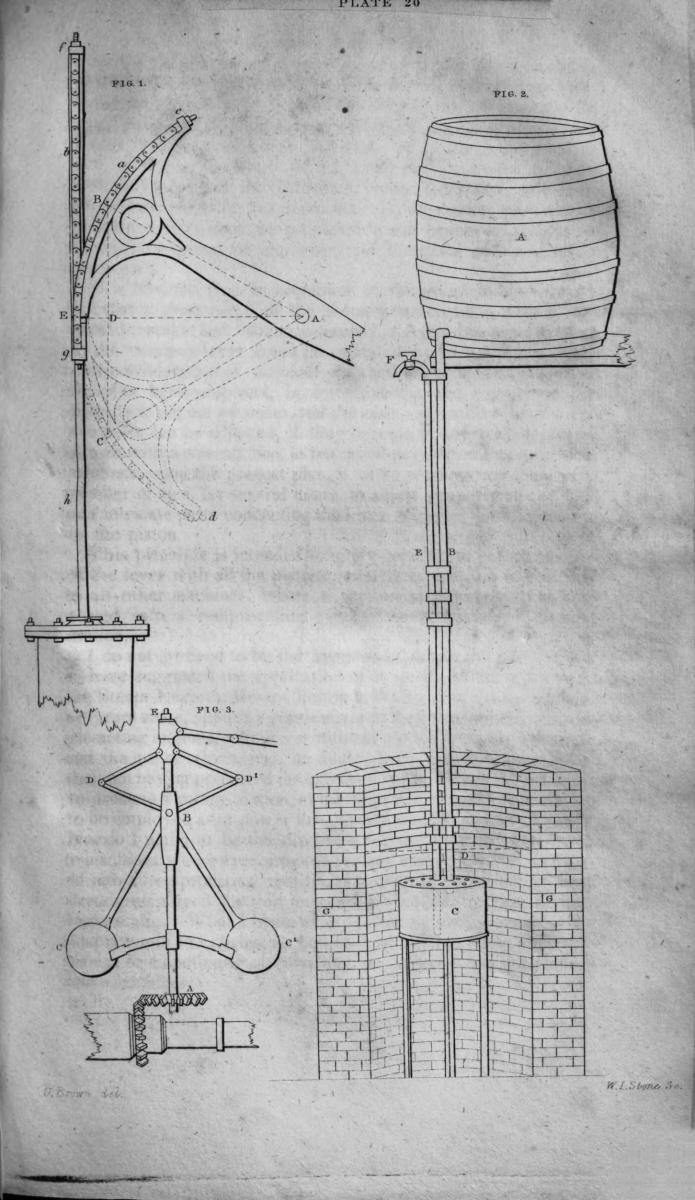
American Journal of Improvements in the Useful Arts, and Mirror of the Patent Office, vol. 1 (Washington, 1828) · View the page
Transcription
Machine-read text of the specification as printed in the Mirror; not proofread.
ae IMPROVEMENT IN STEAM ENGINES, &c. wie a WM By Uriah Brown, of Washington, District of Columbia. ; vi oe hms. ;
HS ‘ See plate XX. fig. 1. te al Specification.—Be it known, that I, Uriah Brown, of the City sof Washington, in the District of Columbia, have invented, or A discovered, a new and useful improvement in the steam engine, denominated “The Double Tangent Chain Lever;” the object heey of which, is to transmit motion and power from the pistontothe hem lever or working beam, and to convert the rectilinear motion of the piston, into a reciprocating circular, or a continuous cireular motion, upon a more simple, economical and efficient principle, __ than any, perhaps, which has been heretofore suggested. it "4 “oa This object, I propose to accomplish, by means of two chains, Be, (a and 6,) alternately working over the periphery of an arc at thie the extremity of the impelled end of the lever. The chains are formed similarly to the common watch-chain, and are each tobe a secured, by one end, to projections, (d and c,) at the extremity of ma the two opposite ends of the arc, by means of regulating screws and nuts; and by the other ends, to opposite vertical points, ; (above and below the arc,) of the cross bars, (f and g,) of an 3 ‘open parallelogram sliding frame; into the centre of which, di- Bg rectly over the piston-rod, (h,) with which it is connected; the a Bi: periphery of the arc projects, and in which it oscillates freely. ee The chains lie parallel with each other and with the motion of the piston, from the two opposite points, where they are inserted _ into the cross-bars of the slide, ’till they meet, or pass each _ other at a tangent point (E) of the arc, horizontal to the fulcrum (A) of the lever; from this point, they follow the periphery of the are to its opposite extremities (c and d), and upon which they act as the agents of communicating motion and power from the piston to the lever, and the parts with which it is connected, : aa by alternately elevating and depressing it; that is, by the upey ward stroke of the piston, the lever is moved from C to B, and Bi by the downward stroke, it is returned again to C. ga The advantages which I contemplate may be derived from ‘a this modification, are, the saving of that portion of the power of the engine, which is lost by the present methods of communicatee ing motion to the lever, by the angle which the comnecting-rod ue makes with the piston-rod, and the lever, at the upper and lower ee points, (B and C,) and by the great degree of friction, which, es - consequently, unavoidably occurs, even in the most approved ee principle which has yet been adopted for preserving a parallel My Cae motion in the piston This saving of power is effected, by rea~ eS son of the chains - working uniformly at a stationary tangential point (E) of the periphery of the arc; the maximum force ofthe ee es. c : me fen as ie ee pas | gees Fini’ ioe” 2 a ee Bi Fe acy pk a" il. ra pt cilia ee. ica oF mR ae i See a t Brae Py Bie He engine being thereby constantly exerted at radius, and the chains. ; rolling alternately on and off the are, at the horizontal point (E), “a maintain a perfectly uniform parallel motion in the piston, with no other. friction than that which is occasioned ‘by the slight _ ge working of the rivets in the. connecting joiuts of the links. In order to illustrate this proposition, and to show the decided superiority of the principle here suggested, over that of the lever in common use—in reference to the common lever, put radius A E=the length of the impelled end of the lever A B; and the Bia sector through which the lever oscillates, from B to , and vice versd,—60 ; that is, 30 above and below the radius or horizon- a tal line A D E. Now, as the piston-rod (h), moves in a tangent Na line to the radius AE, it is manifest that the motion communi- 2 cating power to the lever, at any point (A B), must be ina die al rection parallel to the tangent motion of the piston; therefore, at any point (E), less than radius, the space through which oe the power moves, must be as the right-sine of the angle of ele- tx vation or depression in the lever, and in that direction only; : consequently, the efficient force which is exerted upon the lever im common use, at every increment or decrescent point less than ae radius, is as th co-sine, and the power lost (or ineffectually exerted), as the versed-sine of the angle of elevation or depres- : sion, ; adie aa Puting R= the-radius. A E; : pees Rese w.==the versed-sine D E; of aed ee D ee the co-sine A D; “i : ae ey:
M-= the maximum power exerted at E, — R; Sciam eo. l — the power lost, =v; and. wget. a:
r =the residual power exerted, — c, at Bess itis, M:1::R:0; and M:r:: R: ; or, transposing it, — AS L:M::e: Randr:M:: :R. ' Sar] Putting M = the power of 100 horses, it is, nes @ OS M=1 :l=.1339746 :: M—=100 : L=13.3974600, the horse pow- _ ee erlost; & M1 : r= .8660254 :: M—100 : r—86.6025400, the - a yesidual horse * a applied. But, as this extent of versed-sing, and its consequent proportionate diminution of power, is only of “momentary duration, on the alternation of motion at th extreme zenith and nadir points (B &'C), the mean_ between these two aq points, and the horizontal point (E), at. which the maximum energy of the power is exerted, must be taken as the average loss ‘of force sustained by the common lever—viz: equal to the versed- LRN sine of a fraction more than 21 ; ==6. 6987300. Pursuing, then, eth eas i a op ig ee ER be a the equation, and putting m — the mean loss of power at the ‘i versed sine of 21 , &c. we have, ae 1=13.3974600—im= 6.6987 300—I—6.6987300, the average ey horse. power lost; and ; ss == 86.6025400 ++ m=6.6987300—r=93.3012700, the average horse power exerted. From which, it appears, that the average loss of power, on the common lever, ranging through a space of 60 degrees, is equal to 6. 69 &c. percent; and the average power exerted, equal to 93. 30 &c. per cent, of the maximum power of the engine.
To this loss may be added, that arising from the friction which occurs in maintaining a parallel motion in the piston; particu~ie! larly, when the connecting-rod is at its greatest angle with the piston-rod and the lever, at the upper and lower points (B and mn C); at the very points, too; where friction is interposed to the Soi greatest possible. disadvantage of the engine; for, it is at the ihe very instant, when the efficient -power on the lever is at its min- : Ml imum, and when" the crank at the end of the antagonist lever is an at its dead point, and when, consequently, there. is no efficient ad power exerted upon it, except that which has been previously communicated to the fly-wheel, and by the vis inertia, alone, of ae which, the engine is. relieved’ from the mechanical dilemma in tid * which all these causes have conspired ‘to place it. The power which is thus lost. by friction on the. machinery necessary to maintain a parallel motion in the piston, and its injurious effect upon the crank motion, may, perhaps, ‘be fairly assumed toequal the average loss of power on the lever, as before stated, viz: ==6. 6987300; which, added. to 6.6987300, (the average loss on the lever), is ==15.3974600, the whole amount of horse pow- Bis er lost; equal to 13.39 percent of the maximum power of 100 ee horses. . Consequently, an engine, of the form in common use, computed to be equal to the power of 100 horses, is actually only equal to one of 86.60-100 &c. constructed upon the principles here proposed.
Be: It may, perhaps, be urged as an objection ‘to the. proposed improvement, and as an argument in favor of the present form of steam engines, that it is unnecessary to work the piston through go great a range of stroke; or, if this should ie: a corresponding length of lever may be employed, which would leshee sen the angle of the connecting-rod here mentioned. _I am aware that this may, in some instances, be practicable; but I am equally aware, that, just in proportion as the length of the stroke is “pee reduced, will the recurrence of passing the crank through the oe dead points of its. circle, be increased —a circumstance which 3B ought carefully to be avoided, as far as practicable, by all enia gineers.. A great length of lever is often attended with serious ae ne ret Ser on CE Ey sie eee ee phage sh Se Baa i, a Ng IN Uae Rae aes Was F Ce ee ee aie ee Ani Ree disadvantages; particularly in its application to steam-boats; sik, where, for want of room and other circumstances, the lever, el and eonsequently the length of the stroke, are circumscribed to re small ranges; and the frequent return of the crank to the dead ii points, and the consequent diminution of power is the result.— a But, admitting the length of the lever and the stroke to be in- a) definitely increased, the difficulties, before suggested, will there- A by be only partially, but never entirely, overcome; whilst other ; equally serious ones, are produced by the ponderous weight and IF increased expense of the lever, and the parts with which it is is il connected. had It is obvious, from an inspection of the principle here propos-. that a great range of the piston is practicable, with a very a. small leverage, and that, consequently, the disadvantages incident el to the common lever could be obviated by its adoption. Another consideration of no small practical importance in favour of ees the plan here proposed, is, its simplicity, and consequent less liability to get out of order, and the ease and facility with which a Nag the parts can be adjusted, if they become in any way deranged. can A man with a wrench, can, in ten minutes, perform this operation, whereas, upon the present plan, it often requires the labor of a a number of men, for several hours. to adjust properly all the nice and intricate parts connecting the lever with the parallel motion of the piston. 2 This principle is intended to apply equally to the connection of the lever with all the pistons, constituting a steam engine; and Fe to all other machines, where a rectilinear motion is to become verted into a reciprocating circular, or a continued circular motion. 8 do not pretend to be the inventor of the chain, nor the first to have suggested the application of it singly, to the working of ee the Steam: Engines. Messrs. Bolton & Watt and others having, ma- Se ny years since, applied a single chain to their atmospheric and sin- ea gle-acting engines, where a rectilinear motion was only required, and. the use of which, was, no doubt, discontinued by them, from + a their not having perceived the extended application of the principle Sg al to produce a rotary motion, at the time that steam-engines began a to be employed as a power for general manufacturing purposes. et Nor do I claim to be the discoverer of the adaptation ef chains to machines where a reciprocating rotary motion is to be convert- eS ed into a reciprocating rectilinear motion; chains having been already employed for this purpose, in the construction of fires engines, &c. What I claim as my invention or discovery, is the ~ <i adaptation of two chains, as before described, to effect a al ee : See cating, or a continued circular motion, in steam-engines, and in other machines. a Eye In testimony that the foregoing is a true specification of my said improvement in the lever, as by me described, I hereunto set my hand and seal this twenty-ninth day of August, 1828. In presence of URIAH BROWN. L. 8. _ 4, "CHAS. M. KELLER, aa JONAS KELLER.
PROCESS.OF COOLING WATER AND OTHER FLUIDS.
About this record
- Listed in
- the Mirror of the Patent Office (1828)
- This patent has no X number: it is not in the list of patents restored after the 1836 fire. It is known only from the printed lists named below. The reference number (U…) is the IP Mall’s own.
- Listed in the Journal of the Franklin Institute or the Mirror of the Patent Office at the time of issue.