

Drawings and documents
National Archives restored drawings: drawing
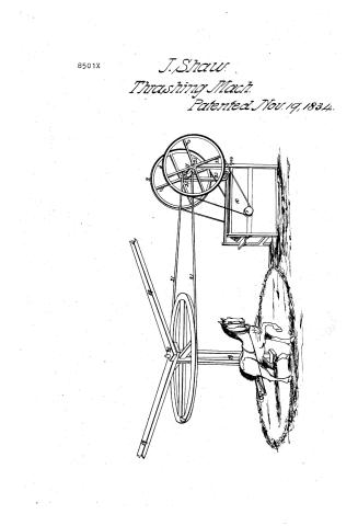
John Shaw's Patent Drawing for a Threshing Machine with Variations for Horse Power

National Archives, Restored Patent Drawings (Record Group 241) · Full-size scan at the National Archives · Catalog record
Show the text on the drawing Hide (255 words)
Words on the drawing as machine-read by the National Archives; not checked. Useful mainly for searching.
130. THRASHING. / Entered / /2- / Thrashing Machines. / cylo / dues not belong to CXXX_ - / A. Cylinder Machines. / JOHN SHAW'S / N°1 The same as N°1 177 the first Drawing / Threshinë Machine with variations for Horse-power. / Qurnswith it / 2.3 The two main propelling wheels upon the Body / 19.17 The Horizoutal outal Horse-Wheel Horse over which passes / N22. A small Will or Pulley onthe mindle of Shaftill. which / the threshing chine of communicating motion to Not / a Banato N.22. / 23. The time backpiosts ofthe main Body of the machine of / & may atpleasure be shifted from No No 25 & vice / N.15. The shaft to which the attached & / equalheight: about/feer. / versa as hand arHorse power is to be applied / which is larned Horse-power applica to N°26 / N°24 Sockers filled ford shaft Noll to revolve in athleasure / The main body of the Machine as in the first drawing / ND_ The Braces by which shaftls iskept stendy / 25. Sockers forciliajte V.II. to revolve 111 when carried / the interior & machinery theren being exactly Similar / N.20. The judgeon or/11001 which revotvesin Braces N19 / Horse-power from which it may be shifted E/ilacen in Nos 24. / N°11 The Shift with which Wheels N.O 283 are connected revolve. / 21. The Band соmшинса tillo from NYTO No 22- / forhand-power / CLASSIFICATION / 26 The arm allached to the perpendicular Shaft to the extreme / 8501-4 / end which the Horse is to be attached / No 27. The Block on which Tests Ate shaft. 18. / DIVISION / I atente a 19 November 1834. / 20 / 21 / 25 / 72. / 21 / 25 / 23 / 23 / 28 / 424 / 724 / 10 / G.S.Del
USPTO scan
The patent as scanned by the USPTO
-
 Page 1
-
 Page 2
-
 Page 3
-
 Page 4
-
 Page 5
-
 Page 6


U.S. Patent and Trademark Office · Google Patents
Show the transcription Hide (1,810 words)
Machine transcription (LightOnOCR) of the pages as scanned by the USPTO, most of them the handwritten copies made when the records were restored after the 1836 fire. Not checked; it can misread handwriting, so compare it with the scan.
Page 1.
8501X
J. Shaw.
Thrashing Mach.
Patented Nov. 19, 1834.
Page 2.
Nov. 19, 1834 8501X
John Shaw of Augusta in the county of Kennebec & State of Maine.
Letters Patent
The schedule referred to in these Letters Patent and making part of the same, containing a description in the words of the said John Shaw himself, of his improvement in a Machine for threshing grain.
To all to whom these Presents shall come
Be it Known, that I, John Shaw of Augusta, in the county of Kennebec and state of Maine have invented a new and useful improvement in a Machine for threshing grain, and the following is a clear, full and exact description of said Machine as invented or improved by me.
The main body of the Machine is framed of strong joice. It is about three feet eight inches high and four feet six inches long. The sides are boarded up and a joice side girr runs horizontally along the side from one corner post to the other, sufficiently high up to permit the four revolving beaters herein after mentioned to revolve on a shaft resting thereon without coming nearer than eight inches from the floor upon which the machine stands. The Machine is about twenty inches wide between side. And both its sides are framed and constructed exactly alike and are kept firmly together by two girts one of which on the front end is placed within six inches of the foot of the posts, and the other is as near the top of the posts at the other or back end of the Machine. Between the posts in the front end and directly above the side girts alone described, a thick board about two feet six inches wide, is fitted to slide in so far as the thickness of the said front posts is to let its inner edge come up flush with the common receiver herein after described, and for this purpose a square piece is cut out of each end of said board so that it may slide between said post and bring up flush against the front face of the front corner post. The board inclines a little downward at its inner edge and is supported in part by a rest directly underneath which is appended to each of said front posts. The common receiver is made of some solid hard w
Drawn
Page 3.
or material, and is hollowed out on its inner side like ninety degrees of a cylinder about two feet in diameter. The ends of this concave receiver are firmly confined to each side of the Machine, by means of the girts and side boards aforesaid, and the inner or hollowed surface of this concave receiver is studded or set thickly but regularly, with square iron teeth, about three inches long above the wood or surface of the receiver. These teeth are made of iron bars about half an inch square, cut off bluntly, and sharpened at the lower end so as to be driven into the receiver about 3 inches, and leave the projecting part without alteration from the state of the Bar. This receiver is so fixed or set in the machine, that the ends are snug to the sides of Body and inclines downwards at its lower extremity sufficiently to render its concavity concentric or nearly so with the shaft first mentioned on which the beaters revolve. The shaft referred to runs across the body of the Machine from side to side, & revolves on boxes fitted to the middle side girts aforesaid, & a small wheel (about nine inches in diameter) is attached to each extremity of the said shaft and plays upon the outside of the Machine. Within the body of the Machine and on the middle of said shaft & firmly attached thereto, is a cross of joice, or a strong framework, locked together so as to present four arms of equal length, at right angles with each other and radiating from the centre of said shaft. These arms project about nine inches, and on the extremity of each is mortised or strongly fastened a piece of hard wood joice about twenty inches long (corresponding with the width of the Machine) and running parallel with the shaft, being confined at the middle to the arm aforesaid and cut so that their ends will not rub against the sides of the Machine. On the exterior face of the four pieces so confined upon the extremity of the arms aforesaid, are set firmly one row of iron teeth, blunt and square as above described, projecting about three inches and extending along the whole length of each of the pieces aforesaid which are parallel with the concave receiver and so fitted that when they revolve with the shaft aforesaid, the teeth thereof shall pass between the teeth set in the receiver, leaving about three sixteenths of an inch space between them, and also about the
Page 4.
same space between the ends of the teeth revolving and the surface
of the receiver. The two small wheels mentioned above, give motion
to the arms and pieces at their extremities (called revolving beaters)
being attached to the same shaft, & the grain enters by the feeding board
passes into the concave receiver and is threshed by the continued blows
of the said revolving beaters & is thrown or conducted off by a con-
ducting board which at one end is elevated about eight inches above
the floor, touching the lower edge of the receiver & inclining downward
to the feet of the back posts and constituting in fact the floor of the
Machine. The four revolving beaters just described turn within an
arched cap or covering of sheet iron or other boards or other suit-
able material confined to the sides and in front terminating from
three to five inches above the feeding board and extending about
half a circle back. The small wheels aforesaid receive their motion
from two large wheels (about six feet in diameter) placed in
the same plane and connected thereto by bands playing over them
respectively. These two large wheels are turned by hand power
and handles are for that purpose appended to them. They are
keyed on to opposite ends of the same shaft in such a manner
that either or both of them may be removed at pleasure. They
rest upon two arms which run out back of the main body of the
Machine supported by braces and keyed on so that they may
be also detached from the machine when desired.
The size of the Machine and of its Machinery may be
varied leaving the different parts made to correspond with each
other and the beaters may be made of iron or wood, or any
solid material (A View of the Machine accompanies this spe-
cification.)
What I claim as new and of my own invention
are the revolving beaters, the shape and structure of the iron
teeth, the manner of applying the hand power, and the cheap
and compact method of constructing the feeding board and
whole Machine.
John Shaw.
Witnesses: H. H. Fuller. Joel Savage. Kennebec Sept. 23. 1854.
Page 5.
108
8501X
Whereas I John Shaw of Augusta, in the county of Kennebec, and State of Maine have invented a new and useful improvement in a Machine for threshing grain, and have heretofore given a particular description & specification of said Machine as subscribed and sworn to the same: Now therefore, Be it known further, that I the said John Shaw, do hereby make the following addition to my former specification aforesaid, and make the following description of a variation in the construction of said Machine, and of the additional machinery by which a horse power may be applied thereto. A part of my said former specification of said Machine as invented by me, that is to say:
The concave receiver, the revolving beaters, the wheels & pulleys attached to the main body of the Machine and the whole interior thereof, is to be constructed as described particularly in my former specification: but the two back posts of the machine may be constructed about seven feet high and a nich or socket may be cut into the back face of said Posts about four feet from their base, so that the shaft, on the extremities of which are the two large wheels with handles, may easily revolve in said sockets and said large wheels be connected by & with the small wheels or pulleys attached to the shaft upon which are the revolving beaters, as before described; and said wheels large & small may be reduced nearly one half in size. The upper end of said back posts are to be grooved or prepared with sockets into which the shaft with the large wheels may be shifted and revolve therein, whenever a horse power is to be applied, which may be done as follows. On the middle of the last named shaft, a small wheel about four five inches in diameter, is confined so, that it will turn the said shaft with the large wheels by its revolutions. Over the last named small wheel passes a band, above the front part of the machine is a horizontal horsewheel, about seven feet in diameter, placed about fifteen feet in front of the machine. Said horizontal wheel (being sufficiently high up for a horse to travel under said band & under the braces herein after mentioned) is connected with said supports.
Page 6.
on a perpendicular shaft seven or eight feet high, which revolve with it, having gudgeons or pivots at each extremity. The upper end thereof revolving in a place fitted for its reception in braces which are above the horizontal wheel & attached to some distant object, and the lower end turning in a block set in the ground for that purpose. From the middle of this perpendicular shaft, a beam or arm extends out seven or eight feet and at the extremity of this arm the horse is to be attached and by means of the usual leading pole and rein may be made to travel in a circle, under the wheel & braces last described. All which is illustrated by the second drawing & explanation accompanying this additional specification, and which is to be considered as connected with the former and made a part of this instrument.
Hereby claiming as new & of my own invention all that I claimed in my first specification, and also the manner of applying horse power to the main Machine.
Witnesses:
H. W. Fuller
H. W. Fuller
Nov. 3rd 1834
John Shaw
Drawing
Ex. 11.
[1924 1082]
Published accounts: journal notice
Notice in the monthly list of patents, with remarks
Journal of the Franklin Institute, new ser., vol. 15 (1835), p. 396 · View the page
17. For a Thrashing Machine; John Shaw, Augusta, Kennebeck county, Maine, November 17.
Remarks. There are to be four beaters, set with teeth, and revolving like a horizontal reel. The teeth are to be of wrought iron, about half an inch square, and to project out from the wooden beaters, about three inches; similar teeth are to be driven into a concave, and the whole is to operate in the ordinary way; the principle of action is precisely the same with that of many other thrashing machines, the points of difference being mere matters of arrangement. The claim is to "the revolving beaters; the shape and structure of the iron teeth; the manner of applying the hand power, and the cheap and compact manner of constructing the feeding board, and whole machine."
Published accounts: specification
Specification printed in the Journal of the Franklin Institute
Journal of the Franklin Institute, new ser., vol. 13 (1834), p. 272 · View the page
Text of the specification as printed in the Journal, from OCR; not proofread.
Specification of a patent for Furnaces for Generating Heat by Friction, and applying the same to economical purposes. Granted to JOHN W. COCHRAN, Lowell, Middlesex county, Massachusetts, November 19, 1834. To all whom it may concern, be it known, that I, John W. Cochran, of Lowell, in the county of Middlesex, and state of Massachusetts, have invented a Friction Furnace for generating heat without the consumption of fuel, and applying the same to economical purposes; and I do hereby declare that the following is a full and exact description of my said invention. Although the fact that heat may be generated by friction is one of universal notoriety, it does not appear that the idea of applying this heat to economical purposes has ever been practically acted upon; I, however, have ascertained by satisfactory experiments that it may be done to great advantage. The most convenient way of effecting the object is to prepare two metallic disks, or cylinders, say of cast iron, in the form of common mill stones, and to cause one of them to revolve against the other, under considerable pressure, which pressure may be given by the weight of one of the disks, or by that of a vessel containing water, or other fluid, to be heated, the bottom of which may take the place of one of the disks; or by weighted levers, or in any other way of producing pressure which may be preferred. When I make two disks of this description to rub against each other, I form one or both of them somewhat hollow towards the centre, on the touching sides, as a bearing on that part would tend WATT's mode of Preparing Tallow. to diminish the friction towards the periphery, where the motion is the most rapid. There are many ways in which I contemplate the application of this principle, as, for example, I intend sometimes to cause two disks, such as I have described, to revolve, one against the other, by power derived from a water wheel, or from any other convenient source, and to enclose them within a drum, or chamber, into which a current of cold air shall be admitted, and whence it shall be conducted by suitable tubes, after it has been heated by being brought in contact with the disks; thus using it to warm the apartments of any building, or for other purposes. Where steam is preferred, I intend sometimes to allow water to fall in a small stream upon the heated disks, and to conduct it thence through tubes to wherever it may be required. Where steam is to be generated to drive machinery, the bottom of the boiler may be made of suitable form, and to bear upon a disk revolving below it; or the bottom may be perforated to allow the shaft of a disk revolving in the inside thereof, to pass through, and to be turned by any suitable apparatus, by power derived from the steam generated by the heat from the friction, or from any other source. These various modes will sufficiently illustrate the principle upon which I depend for rendering the heat which was latent, sensible, and active; but I do not intend by this enunciation to restrict, or confine myself to the form of apparatus herein described, or to the objects to which it may be applied, but to vary the same in any manner which I may find most convenient and efficient. It may at first appear that the powerful friction necessary to engender sufficient heat to be usefully employed as a substitute for that extricated in the combustion of fuel, will produce a rapid wearing out and destruction of the rubbing apparatus; I, however, have ascertained, satisfactorily, that when the metals become heated, there is a degree of repulsion produced between them which admits of but little abrasion of their substance. What I claim as my invention, and for which I ask a patent, is the application of the heat generated by the friction of pieces of metal against each other, to the purpose of heating air, generating steam, and, in fine, to all the economical purposes to which such heat is applicable, proceeding, in its production, upon the principles herein before set forth. JOHN W. COCHRAN. ENGLISH PATENTS. TO CHARLES WATT, Surgeon, for his invention of a new or improved method, or process, of preparing tallow and stuff from fatty materials, and refining the same for the manufacture of Candles, and other purposes. Sealed September 27, 1832. This invention consists in subjecting the rough fat, tallow, stuff, or other fatty materials, to a process of boiling, with water containing a VOL. XIII. No. 4.-APRIL, 1834. 35 WATT'S mode of Preparing Tallow. weak solution of caustic alkali, simple, or compounded with ammonia: small quantities of alkaline solution being occasionally added during such boiling, and great care being taken to avoid saponification; and after the tallow has been liberated from the animal substances, containing gelatin, albumen, fibrin, and colouring matter, it is allowed to settle, and is then submitted to the action of boiling water containing a weak solution of acids, and is kept boiling by a gentle heat (steam being preferred) until the scum on the top of the tallow subsides; and after settling a few minutes, the tallow is again boiled in water, to wash out the acid. In order that my process of preparing tallow may be better understood, I shall more minutely detail it, stating such proportions and quantities of water, alkalies, and acids, used to prepare and refine a given quantity of rough material, as I find best to answer the pu purpose; but I hereby declare that I do not intend to confine myself to the precise quantities and proportions herein stated, as it may be necessary to make some slight variation to suit the different kinds and qualities of the raw material; but I declare that the quantities and proportions herein stated are best suited to the average and ordinary kinds and qualities of the raw material. Having put into the vat or melting vessel a quantity of water, in the proportion of about fifteen gallons to each hundred stone (of eight pounds per stone,) of rough material to be prepared and refined, the water is brought to the boiling point by the aid of steam admitted into the vat in any convenient way, or by the aid of any other means of imparting heat, steam heat being preferred, as it is not so likely to injure the body, texture, or colour, of the tallow, as the direct action of fire. I then introduce into the water in the vat or melting vessel, a solution of alkali, as potash, soda, &c. I prefer it to be caustic; or in lieu of such solution, I introduce into the water in the vat or melting vessel, a quantity of such alkaline earth, or earths, as lime, &c., as will answer the purpose, the solution containing about one pound and a half of alkali to the one hundred stone of fatty materials intended to be prepared or refined. The rough fat having been previously chopped into small lumps, is then let down into the vat or melting vessel, and the whole is made to boil; and during the time it is in a state of ebullition, I add, occasionally, about as much more alkaline solution as will contain about a pound of alkali at each time; and this is to be added at proper intervals, namely, about every fifteen or twenty minutes. This process is to be kept up until the whole of the gelatin, albumen, fibrin, and other animal matter is detached, and until the lumps, or dabs, of fatty materials disappear, and the whole of the tallow rises to the surface of the water, taking great care that no saponification takes place during this process of boiling with the alkaline solution; but should this happen, more chopped fat, or fatty material, is to be added, until the tallow separates, which will be evinced by its rising again to the surface; the whole quantity of alkali required in this process to reduce and prepare a ton of fatty materials, not being more than about six or seven pounds. Sometimes, and more particularly WATT'S mode of Preparing Tallow. when the rough fatty materials are stale, I add about one pound of sub-carbonate of ammonia, or a pint of pure liquid ammonia, to the ton of fat, during this process of boiling. After the rough materials are reduced to the state of melted tallow, that is, when the tallow is liberated from the gelatin, albumen, fibrin, or other gross materials, it is left to settle a short time, that is, until it becomes clear, and is then removed to the refining vat or vessel, which should be formed of wood, or such other material as acids, simple, or compound, do not act upon. Into the refining vessel I previously introduce sufficient water to cover the bottom of it to the depth of about two or three inches, and then add some diluted acid, and boil the whole, by steam, or otherwise, until all the scum on the tallow subsides. The diluted acid which I use to each ton of tallow, is about three pounds of sulphuric acid diluted with three gallons of water. In the event of there being more rough materials to be melted or prepared, the water and alkali, (which, from being the heavier, will be found at the bottom of the vessel under the detached animal matter,) are to be pumped or drawn off, leaving in the melting vat or vessel the solid parts, lest they should contain some dabs or lumps of fat, or should, from their being thick, retain some melted tallow among them. Fresh water, in quantities as at first, and alkaline solution, or alkaline earth, as before mentioned, are then to be added, and the process to be regulated precisely as before; when the whole quantity is completed, then the under water is to be again pumped or drawn off, and if any dabs or lumps remain, fresh water is to be added to them, and alkaline solution in half the quantity to that employed upon the fresh fat: regulating that quantity according to the amount of dabs or lumps remaining. The solid, or gross parts, left after all the tallow is reduced, and liberated therefrom, may be dried by a gentle heat, and pressed into greaves, or used for any other purpose for which animal matter is adapted. The scum being boiled down, the second part of my process is a good criterion that the tallow is in a fit state to settle. When the tallow has been boiled with the diluted acids, in the second part of this process, and has sufficiently subsided, it is conveyed to another vessel, where it is submitted to the action of boiling water for a few minutes, which will wash the tallow free from any acid that may be mixed up with it. The water in this vessel is also boiled by steam, and if the ebullition should not be sufficient, it may be kept stirred up during the time it is boiling; and when the tallow has sufficiently settled after this third boiling, it is drawn off into the coolers, and when properly reduced in temperature, may be packed off in the usual manner. I prefer the use of steam heat to boil the materials in my improved process, as it is not so likely to injure the body, colour, or texture, of the tallow. [Lond. Jour. TO WILLIAM GRATRIX, silk dyer, for his invention of an improved method of imparting to various woven fabrics, or to the yarns or threads of which the same are intended to be composed, the colour necessary to form the required patterns thereon. Sealed January 5, 1833. The invention described under this patent, is for a new method of applying the colour to piece goods in general, and is effected by the following means: the pattern with which the goods are intended to be wrought, is first cut out of a thin sheet of copper, tin, or other metal, or mixture of metals, or it may be cut out of a square of silk, stout paper, or any material which is suited to the purpose, but which must first be rendered impermeable to the colour by oils, varnish, &c. The sheet, with the pattern cut out of it, is then to be mounted on one side of a frame, and the flat side of the frame and sheet placed upon the silk, or other piece goods to be wrought with the intended patterns, which goods must be previously stretched upon a plane or table fit to receive them; the colour is then rubbed over the whole surface of the sheet of metal containing the pattern, with a brush or otherwise, (in the manner of stencilling,) or the colour may be communicated through the medium of a felt absorbed with colour, and subjected to a slight pressure, such as the blow of a hammer, or a gentle pressure in any other way. This process will leave the pattern only upon the goods, the intervening surfaces of the sheet preventing the colour from marking any part of the goods but those exposed by the removal of part of the sheet of metal in cutting out the pattern. It must be quite evident that this process is the mere adaptation of the art called "stencilling," to piece goods; which process has been adopted generally for many years, as a cheap mode of covering walls of rooms with patterns, to supersede paper hanging. It is also evident that this process would produce much the same effect as block printing in common, as many colours may be worked upon the same ground by the intervention of surfaces, containing different patterns cut therein, to suit the different colours and shades required for the completion of the pattern upon the piece goods. [Ibid. T TO WILLIAM W. TAYLOR, felt manufacturer, for his invention of an improved cloth for the sails of ships and other vessels. Sealed November 8, 1832. This invention consists in the application of a cloth or fabric made of hair, for constructing sails for ships or other vessels. The hair used for this purpose may be of such kind as is cheapest, and commonly found in the market, as ox and cow hair, which is usually employed by mixing it with mortar for plasterers' use, the short staple hair of horses, and that of the calf, the elk, or any short staple hair that may be found useful for the purpose. The hair is combed and carded, as in woollen manufactures in ge1 neral, then taken off in slivers, and after being spun into yarn, it is to be wove into cloth or fabric by means of a common hand loom, or otherwise. The patentee prefers that the warp threads should be made of two threads or yarns doubled or twisted together, and that the weft should also consist of two threads twisted together, that mode being the strongest and by far the most preferable. The cloth, or fabric, is to be subjected to the process of fulling, as usual in woollen manufactures, which will render it a perfect material, and capable of holding the wind as well as the common sail cloth made from hemp or flax, if not much better. Sail cloth made in this manner, and of this material, will not be subjected to the ill and rotting effects of mildew, damp, &c., but will perfectly resist the same. The cloth, or fabric, is to be cut up and made into sails of the suitable and required shape, and the parts, or pieces, are to be sewn together by a thread made of similar hair to the cloth, and should also consist of two threads doubled or twisted together. Sails made upon this improved plan will be totally free from the danger of the effects of damp, mildew, &c., which is the cause of the rotting of the sails now in use. [Ibid. TO SHERMAN CONVERSE, gentleman, for an invention communicated to him by a certain foreigner residing abroad, for certain improvements in making or manufacturing metallic rails, for the construction of railroads. Sealed September 29, 1832. The improvements in rail-roads, described in the specification of this patent, is the application of longitudinal bars of iron, placed as tension rods under the rail, and from chair to chair successively, through the whole length of the line of rail-roads, so as to secure the chairs longitudinally; and also in the application of cross tension rods, or stretchers, to be placed transversely between the chairs and rails, so as to connect the whole crossways, and form a perfect security throughout the line; these cross tension rods acting at the same time as a stay and a brace; the whole being firmly connected by bolts, and secured by screw nuts, wedges, or otherwise, as may be found the most desirable, in the application of the same. [Ibid. Magnetic Experiments on Chronometers. (Concluded from p. 208.) The result of our experiments, however, with our patent balance, was sufficiently satisfactory to persuade us that we had entirely obviated the difficulties under which we previously laboured when the steel balance was employed. We then proceeded to apply it to a chronometer, and, with a view to establish our opinions of its correctness with still greater certainty, we resolved to follow up the question of magnetism by inquiring how far the rate of a chronometer was influenced by the interference of an artificial magnet, when the old and new balances were applied. We accordingly made two chronometers on the old principle, the balance and spring in one of them being composed of steel, with a brass outer circle, and the other a patent balance of steel. We then made two on the new principle, with a gold spring, and a balance of platinum, silver, and brass, and assuming the non-magnetic power of these latter chronometers, and with a view to determine the relative magnetic influence exerted on the steel spring and steel balance respectively, we had one chronometer with a steel balance and gold spring, and the other with a steel spring, and balance of platinum and silver. In the former case, the deviation in rate would be attributable to the steel balance, and in the latter to the spring. Six other chronometers, varying in the different alloys employed in the gold spring, and other particulars, were constructed, and the twelve were, by permission of the Lords of the Admiralty, placed at the Royal Observatory for trial. The majority of these being entirely new chronometers, and, in fact, all of them, except 521, being made within the last two years, we were desirous, previous to the application of the magnet, &c., to have five or six months' rates, and the results were published in your Magazine for February. After this trial, we chose out of these twelve chronometers some constructed on the principles above mentioned, with a view to place them in contact with the magnet. Those selected were Nos. 606, 605, 615, 657, 600, and 274.* No. 606 and 605, have gold springs, and balances of platinum, silver, and brass. Nos. 615 and 657, have steel springs and steel balances. No. 600 has a steel spring, and balance of platinum, and silver: and, lastly, 274 has a gold spring and steel balance. It may be necessary to remark, that No. 615 has a patent balance, the upper bar of steel, and the lower bar of brass; and this circumstance will account for the difference in the effect produced upon this chronometer, and No. 657, which has a balance on the old construction, with an arm entirely of steel, and the inner circle a rather stout lamina of steel, and the outer of brass. The steel bars employed, marked in the table of experiments A B and C, were each 16.12 inches in length, 1.68 inch in breadth, and 0.44 inch in thickness, and were strongly magnetised. Great care was taken, when the magnets were not employed, to preserve their virtues uninjured. They were therefore placed in a deal box, to keep them from the dampness of the atmosphere, though, from their highly polished state, they could not contract much rust, and their opposite poles were connected by two bars of soft iron, so as to form, when in this position, the figure of a parallelogram. It will here be necessary to recapitulate a part of our former statement relative to the particul
About this record
- Patentee
- Jim Shaw's X-patent list
- Date
- the Name and Date index of patents, USPTO records, Jim Shaw's X-patent list
- Invention
- the Name and Date index of patents
- Listed in
- the Name and Date index of patents, USPTO records, Jim Shaw's X-patent list, the Journal of the Franklin Institute, Burke's List of Patents (1847), the Journal of the Franklin Institute, Journal
- The residence comes from the Franklin Institute's journal.
- The Franklin Institute's journal gives a different date.
- Burke's 1847 Patent Office list gives the same patent.