

Drawings and documents
USPTO scan
The patent as scanned by the USPTO
-
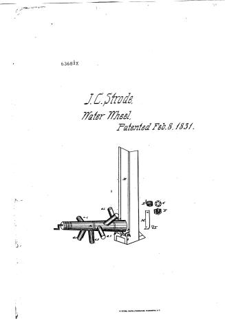 Page 1
-
 Page 2
-
 Page 3
-
 Page 4


U.S. Patent and Trademark Office · Google Patents
Show the transcription Hide (1,180 words)
Machine transcription (LightOnOCR) of the pages as scanned by the USPTO, most of them the handwritten copies made when the records were restored after the 1836 fire. Not checked; it can misread handwriting, so compare it with the scan.
Page 1.
6368½X
J.C. Strade,
Water Wheel,
Patented Feb. 8, 1831.

R. PETERS, PHOTO-LITHOGRAPHER, WASHINGTON, D.C.
Page 2.
Feb 8 1831
Joseph C. Stowe
Letter Patent
6368 ½ X
The defendant referred to in the Letter Patent and making part of the same containing a description in the name of the said Joseph C. Stowe himself of his improvement in the machine for supplying saw mills & other works by water called Stowe’s Reaction Water Wheel and specifies in the words following:
I, Joseph C. Stowe of East Brunswick in the county of Hunterdon and state of Pennsylvania Teacher and grating. Do it known that I Joseph C. Stowe have invented, constructed and effected to use a new and useful machine for supplying saw mills & other works by water called Stowe’s Reaction Water Wheel and specifies in the words following:
It is a wooden shaft having in its larger end a conical hole of such diameter as to fit the larger end of the shaft and a socket at the smaller end of the shaft to receive a conical hole of such diameter as to fit the larger end of the shaft and a socket at the other. The area of the hole will vary directly as the square of the radius of the shaft and inversely as the circumference ratio of the height …
Page 3.
2/8/1831 6368
such as increases the length and would not spring against the head of the engine. I think perhaps at bottom, so that if the number of arms be increased the length of the shaft must be increased in proportion. The arms are made fast on the shaft by means of a tenon with a dove tail as represented by figure 22. The side of the tenon on which the dove tail is made is rather narrower than the opposite side. If the mould on the shaft is of the same shape so that when the wing D is driven on on the side opposite to the dove tail it will be found tight on all sides.
B is a hollow cylinder eight inches in length with a rim on one end one inch and a quarter wide & three quarters of an inch thick. The diameter of the hole is eight inches the same as that in the shaft A. The diameter from end to end is nine inches and a half, half its length. The other half or the part b, is nine inches and a quarter at the shoulder where g, terminates, tapering to the end where it is nine inches. This cylinder is let into the plank D of the trough a hole is then made thick with its rim on the inside which is sunk in the plank three quarters of an inch deep so as to face with the inside of the plank. It is made at the same time firm & water tight by means of eight scows bolts, each three inches and a half long driven in from the outside thru' holes made in the rim where by g, is secured sufficiently and rendered tight by means of nuts. The part b, is four inches in length and goes into the cylinder B, which is of the same length. It is made fast in the shaft. It has four wings to keep it from turning. This cylinder is of such a capacity that it will work easily on the part b, and at the same time not allow too much play. It is a lead screw one inch and a quarter wide, three eighths of an inch thick and it runs down the eight inches. The number and arrangement of the arms dimensions are secured against the ends of b, and B (which are turned so as to face exactly) by means of eight scows going thru' them and coming into the end of b,. This is in order to work water tight. B is a cast iron friction wheel fourteen inches in diameter running with its periphery against a turned iron against the iron head f, on the shaft of the hand lever (also turned) firmly and preventing the wings of the shaft a, b, from moving too much friction on the gear gear h, of figure 22. The gearing of the gears is such as to have on the outside of the two wings from a, b, a width of iron which is supported by the eight scows h, of plank b, one inch thick, and secured the better
Page 4.
4/8/1831 6368 12x 307
to the axle to be made from at the top by the wind wheel c, going over from one to the other and similar to each. On the foregoing description are given the dimensions of a machine in one operation for inscribing a line millimeter line of twenty feet. If a larger or smaller wheel is required, the dimensions of the conical parts will vary according to the proportions given. Some additional power may be obtained by the application of a funnel to each of the holes in the ends of the arms a, a, a, a, a, the small end of the funnel being applied to the hole and the wide end standing outwards. These funnels may be made of small blocks of wood with a hole bored thru the one side of each and hollowed on the inferior side so as to fit the arms to which they may be attached firmly by nails or screws. The holes in the blocks should correspond in capacity & position on the inferior side with the holes in the arms and should gradually widen on the line funnel shape toward the exterior surface of the blocks. These funnels may or may not be attached at the option of the constructor. The machine will operate very well without them, though it believes from experiment with some increase of power with them. If a reciprocating movement is desired it may be obtained by means of a crank on the axle of the shaft d. In the machine above described the crank is at the end of the axle, but if the axle a little prolonged be made to work on a point fixed in a permanent block placed directly opposite the smaller extremity of the shaft d in the intermediate space between the end of the shaft & the block the axle be so shaped as to form a crank by which the reciprocating movement may be given. This will be less friction & consequently a gain of power.
In testifying that the above is a true specification of my said invention in above described I have here to set my hand & seal this twelfth day of January in the year of our Lord one thousand eight hundred & thirty one.
Wm. A. Collins
Inventor
Stephen G. Morse
Ex. 2
M.W.
Published accounts: journal notice
Notice in the monthly list of patents, with remarks
Journal of the Franklin Institute, new ser., vol. 7 (1831), p. 369 · View the page
11. For a Reaction Water Wheel, for impelling saw mills and other works; Joseph C. Strode, East Bradford Township, Chester county, Pennsylvania, February 8.
Remarks. (See the specification.)
Published accounts: journal notice
Notice in the monthly list of patents, with remarks
Journal of the Franklin Institute, new ser., vol. 7 (1831), p. 381 · View the page
The churn is the common dasher churn, the rod of which is to be worked up and down by a pendulum. A frame is to be made, across the upper part of which there is to be a shaft turning upon gudgeons; from this hangs a weighted pendulum. The shaft is crossed by a lever, one end of which is attached to the dasher rod; from the other a pitman descends to a treadle. The pendulum may be made to vibrate by the hand; or the foot may be placed upon the treadle for the same purpose. The claim is to "the application of the pendulum principle to the dasher, which equalises the power applied, and assists in passing the reacting points in the rise and fall of the dasher; and also in the application of the foot power, which relieves the arms and chest in the act of churning." We apprehend that this machinery would be improved by removing the frame, the shaft, the pendulum, the pitman, and the treadle, and taking hold of the dasher by the hands, as dairy maids have been in the practice of doing from time immemorial. SPECIFICATIONS OF AMERICAN PATENTS. Specification of a patent for a Machine for Impelling Saw Mills and other works by water, called Strode's Reaction Wheel. Granted to JOSEPH C. STRODE, Teacher, East Bradford, Chester county, Pennsylvania, February 8, 1831.
Remarks. THERE is a wooden shaft seven feet six inches long, sixteen inches in diameter at the larger end, and fourteen at the smaller; in the centre of this shaft, is made a round hole eight inches in diameter at the larger end, and six at the other; the area of this hole will vary directly as the power required, and inversely as the subduplicate ratio of the height of the head above the centre of the shaft. a, a, a, a, are six hollow arms, six inches in diameter, set perpendicularly in the shaft, A, at equal angular and linear distances, forming a true spiral curve from one end to the other. The holes through these arms are three and a half inches in diameter. Near the end of each arm is a hole one and three-quarters inch in diameter, so situated that the axis of the shaft, A, is perpendicular to the plane passing through the axis of the hole and that of the arm, and so that a plane passing through the axis of the hole perpendicular to the aforesaid plane, shall be a tangent to the circle formed by the middle point in the axis of the hole, by the revolution of the machine on its axis. The distance of the centre of this hole from the centre of the shaft, is thirty-three inches, and will vary directly as the power required and the subduplicate ratio of the height of the head above the centre of the shaft, A, and inversely as the number of revolutions desired. The area of the hole will vary inversely as the subduplicate ratio of the height of the head, and directly as the power required. The distance between each two of the planes passing through the axis of the arms to which the axis of the shaft, A, is perpendicular, is eleven inches, and will not answer to be nearer, because the water from each arm nearer the larger end would impinge against the back of the next arm, and thereby impede its motion; so that if the number of arms be increased, the length of the shaft must be increased in proportion. The arms are made fast in the shaft by means of a tennon with a dovetail, as represented by figure H, the side of the tennon on which the dovetail is made is rather narrower than the opposite side, and the mortise in the shaft is of the same shape, so that when the wedge, I, is driven in on the side opposite to the dovetail, it will be firm and tight on all sides. B, is a hollow cylinder eight inches in length with a rim on one end, one inch and a quarter wide, and three-quarters of an inch thick. The diameter of the hole is eight inches, the same as that in the shaft A. Its diameter from out to out is nine inches and a half, half its length; the other half, or the part h, is nine inches and a quarter at the shoulder where g terminates, tapering to the end, where it is nine inches. This cylinder is let through the plank, STRODE'S Reaction Wheel. D, of the trunk, which is three inches thick, with its rim on the inside, which is sunk in the plank three-quarters of an inch deep, or so as to face with the inside of the plank. It is made at the same time firm and water tight by means of eight screw bolts, each three inches and a half long, driven in from the outside through holes made in the rim, where it is screwed up firmly and rendered tight by means of burs. The part h, is four inches in length, and goes into the cylinder, F, which is of the same length, and is made fast in the shaft. It has four wings to keep it from turning. This cylinder is of such a capacity that it will work easily on the part h, and at the same time not allow too much play. G, is a lead washer one inch and a quarter wide, three-eighths of an inch thick, and its inner diameter eight inches. This washer and an iron follower of the same dimensions, are screwed against the ends of h and F, (which are turned so as to face exactly,) by means of eight screws going through them and securing into the end of h. This is in order to render them water tight. B, is a cast iron friction wheel, fourteen inches in diameter, running with its periphery, which is turned true, against the iron band F, on the shaft, (the band being also turned,) thereby supporting the weight of the shaft, A, to prevent too much friction on the gudgeon, h, of figure E. The gudgeons of the friction wheel run on the middle of the two cross pieces, d and e, made of wood, which are supported by the upright pieces, b, b, of plank, two inches thick, spiked at the bottom to the sill, C, and made firm at the top by the inch board, c, going across from one to the other and nailed to each. In the foregoing description are given the dimensions of a machine now in operation, for impelling a saw mill under a head of twenty feet. If a larger or smaller wheel is required, the dimensions of the several parts will vary according to the proportions given.
Published accounts: specification
Specification printed in the Journal of the Franklin Institute
Journal of the Franklin Institute, new ser., vol. 7 (1831), p. 382 · View the page
Text of the specification as printed in the Journal, from OCR; not proofread.
Specification of a patent for a Machine for Impelling Saw Mills and other works by water, called Strode's Reaction Wheel. Granted to JOSEPH C. STRODE, Teacher, East Bradford, Chester county, Pennsylvania, February 8, 1831. THERE is a wooden shaft seven feet six inches long, sixteen inches in diameter at the larger end, and fourteen at the smaller; in the centre of this shaft, is made a round hole eight inches in diameter at the larger end, and six at the other; the area of this hole will vary directly as the power required, and inversely as the subduplicate ratio of the height of the head above the centre of the shaft. a, a, a, a, are six hollow arms, six inches in diameter, set perpendicularly in the shaft, A, at equal angular and linear distances, forming a true spiral curve from one end to the other. The holes through these arms are three and a half inches in diameter. Near the end of each arm is a hole one and three-quarters inch in diameter, so situated that the axis of the shaft, A, is perpendicular to the plane passing through the axis of the hole and that of the arm, and so that a plane passing through the axis of the hole perpendicular to the aforesaid plane, shall be a tangent to the circle formed by the middle point in the axis of the hole, by the revolution of the machine on its axis. The distance of the centre of this hole from the centre of the shaft, is thirty-three inches, and will vary directly as the power required and the subduplicate ratio of the height of the head above the centre of the shaft, A, and inversely as the number of revolutions desired. The area of the hole will vary inversely as the subduplicate ratio of the height of the head, and directly as the power required. The distance between each two of the planes passing through the axis of the arms to which the axis of the shaft, A, is perpendicular, is eleven inches, and will not answer to be nearer, because the water from each arm nearer the larger end would impinge against the back of the next arm, and thereby impede its motion; so that if the number of arms be increased, the length of the shaft must be increased in proportion. The arms are made fast in the shaft by means of a tennon with a dovetail, as represented by figure H, the side of the tennon on which the dovetail is made is rather narrower than the opposite side, and the mortise in the shaft is of the same shape, so that when the wedge, I, is driven in on the side opposite to the dovetail, it will be firm and tight on all sides. B, is a hollow cylinder eight inches in length with a rim on one end, one inch and a quarter wide, and three-quarters of an inch thick. The diameter of the hole is eight inches, the same as that in the shaft A. Its diameter from out to out is nine inches and a half, half its length; the other half, or the part h, is nine inches and a quarter at the shoulder where g terminates, tapering to the end, where it is nine inches. This cylinder is let through the plank, STRODE'S Reaction Wheel. D, of the trunk, which is three inches thick, with its rim on the inside, which is sunk in the plank three-quarters of an inch deep, or so as to face with the inside of the plank. It is made at the same time firm and water tight by means of eight screw bolts, each three inches and a half long, driven in from the outside through holes made in the rim, where it is screwed up firmly and rendered tight by means of burs. The part h, is four inches in length, and goes into the cylinder, F, which is of the same length, and is made fast in the shaft. It has four wings to keep it from turning. This cylinder is of such a capacity that it will work easily on the part h, and at the same time not allow too much play. G, is a lead washer one inch and a quarter wide, three-eighths of an inch thick, and its inner diameter eight inches. This washer and an iron follower of the same dimensions, are screwed against the ends of h and F, (which are turned so as to face exactly,) by means of eight screws going through them and securing into the end of h. This is in order to render them water tight. B, is a cast iron friction wheel, fourteen inches in diameter, running with its periphery, which is turned true, against the iron band F, on the shaft, (the band being also turned,) thereby supporting the weight of the shaft, A, to prevent too much friction on the gudgeon, h, of figure E. The gudgeons of the friction wheel run on the middle of the two cross pieces, d and e, made of wood, which are supported by the upright pieces, b, b, of plank, two inches thick, spiked at the bottom to the sill, C, and made firm at the top by the inch board, c, going across from one to the other and nailed to each. In the foregoing description are given the dimensions of a machine now in operation, for impelling a saw mill under a head of twenty feet. If a larger or smaller wheel is required, the dimensions of the several parts will vary according to the proportions given. Some additional power may be obtained by the application of a funnel to each of the holes in the ends of the arms, a, a, a, a, &c. the small end of the funnel being applied to the hole, and the wide end standing outward. These funnels may be of small blocks of wood with a hole bored through the middle of each, and hollowed on the inferior side so as to fit the arms to which they may be attached, firmly, by nails or screws. The holes in the blocks should correspond in capacity and position on the inferior sides with the holes in the arms, and should gradually widen in the true funnel shape towards the outer surface of the blocks. These funnels may, or may not, be attached, at the option of the constructor; the machine will operate very well without them, though it is believed, from experiment, with some increase of power with them. If a reciprocating motion is desired it may be obtained by means of a crank on the axle of the shaft A. In the machine above described the crank is at the end of the axle: but if the axle a little prolonged, be made to work on a point fixed in a permanent block placed directly opposite the smaller extremity of the shaft, and in the intermediate space between the end of the shaft and the block, the axle be so shaped as to form a crank, by which the reciprocating Tuck's Stoves, or Flues for Curing Tobacco. movement may be given, there will be less friction and-consequently a gain of power. H JOSEPH C. STRODE. Strode's Reaction Wheel. G F h E I A D B de
About this record
- Patentee
- the Journal of the Franklin Institute, Journal
- Date
- the Name and Date index of patents, USPTO records, Jim Shaw's X-patent list
- Invention
- the Name and Date index of patents
- Listed in
- the Name and Date index of patents, USPTO records, Jim Shaw's X-patent list, the Journal of the Franklin Institute, Burke's List of Patents (1847), the Journal of the Franklin Institute, Journal
- The index's second listing was used.
- The patentee's full name comes from the Franklin Institute's journal.
- The residence comes from the Franklin Institute's journal.
- Burke's 1847 Patent Office list gives the same patent.