

Drawings and documents
National Archives restored drawings: drawing
John Patridge's Patent Drawing for the Manufacture of Wooden Ware without Staves

National Archives, Restored Patent Drawings (Record Group 241) · Full-size scan at the National Archives · Catalog record
Show the text on the drawing Hide (36 words)
Words on the drawing as machine-read by the National Archives; not checked. Useful mainly for searching.
142. WOOD TURNING. / Regular Forms. / Longitudinal Movement. / ys. / $150 / CLASSIFICATION / 6485-+ / DIVISION / Meanufacture Hooden ware without Slaves. / John Latridge / Valented 16 april 1831, / ip / 11
USPTO scan
The patent as scanned by the USPTO
-
 Page 1
-
 Page 2
-
 Page 3
-
 Page 4


U.S. Patent and Trademark Office · Google Patents
Show the transcription Hide (855 words)
Machine transcription (LightOnOCR) of the pages as scanned by the USPTO, most of them the handwritten copies made when the records were restored after the 1836 fire. Not checked; it can misread handwriting, so compare it with the scan.
Page 1.
6485X
J. Patridge,
Making Wooden Trays, &c.
Patented Apr. 16, 1831.

A.M. PHOTO-LITHO. CO. N.Y. (OSBORNE'S PROCESS)
Page 2.
April 16, 1831
6485x John Patridge of Zanesville, Ohio
Letters Patent
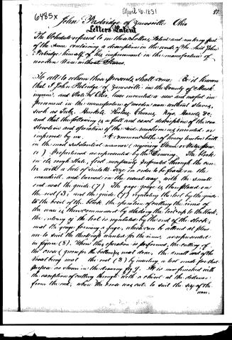
The Schedule referred to in these Letters Patent and making part of the same containing a description in the words of the said John Patridge himself of his improvement in the manufacture of wooden Ware without Staves.
To all to whom these presents shall come, Be it known that I John Patridge of Zanesville in the County of Muskingum, and State of Ohio, have invented a new and useful improvement in the manufacture of wooden ware without staves, such as Jugs, Buckets, Pottles, Churns, Kegs, Barrels, &c, and that the following is a full and exact description of the construction and operation of the said machine as invented, or improved by me.
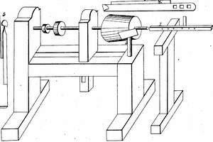
A common Saddle of heavy timber built in the most substantial manner (requiring Steam or Water power) proportioned as represented by the Drawing. The block in its rough State, first necessarily perforated through the center with a hole of suitable size in order to be placed on the mandril, and turned in the usual way with the small end next the guide (7). The gage gauge is then placed on the rest (3), and the guide (7) regulating the slot by the guide to the back of the block. The operation of cutting the rims of the ware is then commenced by sliding the tool up to the block, the cutting of the tool is regulated by the end of the block, next the gauge forming a gage, which can be altered at pleasure to suit the thickness wanted for the rims, as represented in figure (8). When this operation is performed, the cutting of the cross (groove for the bottom) is next done, the small end of the vessel being next the rest (3) by inserting a tool made for that purpose as shown in the drawing fig 9. It is now finished with the exception of cutting through with a chisel at the distance from the end, where the cross was cut, to suit the size of the ware.
Page 3.
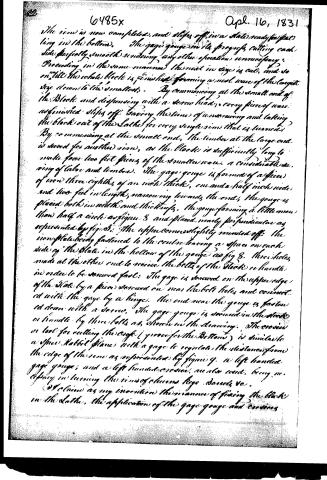
The rim is now completed, and steps off in a state ready for patting in the bottom. The gage gauge in its progress cutting each side perfectly smooth rendering any other operation unnecessary. Proceeding in the same manner the next in size is cut, and so on, till the whole block is finished forming a neat ware of the largest size down to the smallest. By commencing at the small end of the block and dispensing with a screw head, every piece of ware unfinished steps off saving the time of unwrapping and taking the block out of the lathe for every single rim that is turned. By commencing at the small end, the timber at the large end is saved for another rim, as the block is sufficiently long to make four to six feet pieces of the smaller ware, a considerable saving of labor and timber. The gage gauge is formed of a piece of iron three eighths of an inch thick, one and a half inch wide and two feet in length, narrowing towards the ends, the gauge is placed both in width and thickness, the gauge forming a little more than half a circle as figure 8 and placed nearly perpendicular as represented by fig. 3. The upper corner slightly rounded off. The iron plate being fastened to the center leaving a space on each side of the plate in the hollow of the gauge as fig. 8. Three holes made at the other end to receive the bolts of the stock or handle in order to be secured fast. The gage is secured on the upper edge of the plate by a piece secured on near the bolt holes and connected with the gage by a hinge. The end near the gauge is fastened down with a screw. The gage gauge is secured in the stock or handle by three bolts as shown in the drawing. The cross or tool for cutting the edge (groove for the Bottom) is similar to a spur Rabbit plane with a gage to regulate the distance from the edge of the rim as represented by figure 9. A left handed gage gauge, and a left handed cross, are also used, being necessary in turning the rims of churns, kegs, barrels, etc.
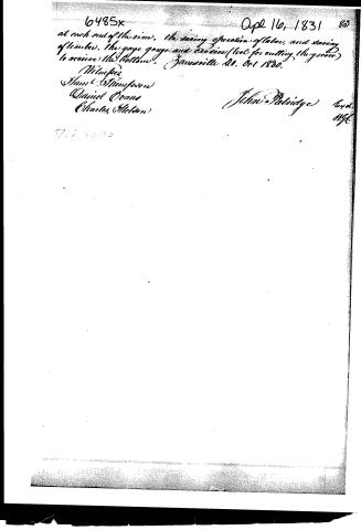
I claim as my invention the manner of fixing the block in the lathe, the application of the gage gauge and various
Page 4.
6485x
Apr 16, 1831 80
at each end of the rim, the saving operation of labor, and saving of timber, the gage gouge and crozier (tool for cutting the groove) to receive the bottom. (Jamesville 21, Oct. 1830.)
Witness,
Sam L. Thompson
Daniel Evans
Charles (Hilton)
John Patridge
Gov.
M.V.C.
Published accounts: journal notice
Notice in the monthly list of patents (listed with a different spelling or date)
Journal of the Franklin Institute, new ser., vol. 8 (1831), p. 122 · View the page
For manufacturing Wooden Ware without Staves; John Patridge, Zanesville, Muskingum county, Ohio, April 16.
DATAMP: illustration
Illustrations from DATAMP

DATAMP (Directory of American Tool and Machinery Patents), via the Internet Archive · Archived DATAMP page
About this record
- Patentee
- DATAMP
- Date
- the Name and Date index of patents, DATAMP, USPTO records
- Invention
- DATAMP
- Listed in
- the Name and Date index of patents, DATAMP, USPTO records, Jim Shaw's X-patent list, the Journal of the Franklin Institute, Journal, Burke's List of Patents (1847)
- Also listed in a contemporary journal or list under a different spelling or date; the record shown follows the standard lists.
- Burke's 1847 Patent Office list gives the same patent.