

Drawings and documents
National Archives restored drawings: drawing
John Jewett's Patent Drawing for an Improvement in the Mode of Causing Cloth to Pass and Be Stretched Whilst Passing Over a Revolving Cylinder Prepared with Paints or Teasles for Teasing or Raising the Pile or Nap Upon Cloth


National Archives, Restored Patent Drawings (Record Group 241) · Full-size scan at the National Archives · Catalog record
Show the text on the drawing Hide (132 words)
Words on the drawing as machine-read by the National Archives; not checked. Useful mainly for searching.
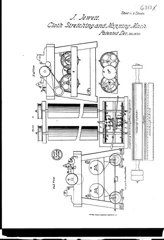
Sheet 1. oth. / 26. CLOT a. / [37] Stretching / [37] Napping / JOHN JEWETT'S / Improvement ment in the mode of causing cloth to pass and be stretched whilst passing over a revotving Cylinder prepared / #6313X / will points or teastes for teasing or raising the pile or nap upon Cloth / PLAN / Patented 30thDecember 7830.00 / DIVISION. / End View / End View / 19 / 41 / 41 / 355 / 18 / 16 / 17 / 15 / 38 / 36 / 14 / 37 / 39 / 21 / 14 / 20 / 13 / of / End of / Nappurg Cylinden / 22 / 12 / 34 / 24 / 22 / 6cc / c.c.D / a.d / 0 a.a / 29 / 30 / V.V. are Friction Wheels / G. / GroundView of Geers. Driving pulleys& change motion / Napping Cylinder / by / DEPORTMENT / Napper / Section op The Brush / seale / 1/2 / to
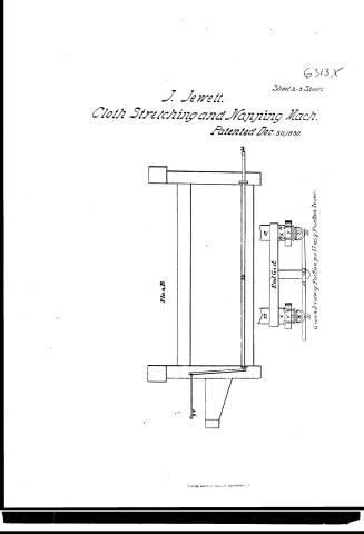
Sheet 2. CLASSIFICATION / 6313Y / DIVISION. / No 2 / PLAN B / yy / 33 / 22 / 12 / End / Girt / 24 033 / Ground View of Friction pullies & Frection.Lever
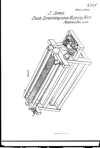
Sheet 3. CLASSIFICATION / 6313X / PLAN C / DIVISION. / N°.3. / OIR
USPTO scan
The patent as scanned by the USPTO
-
 Page 1
-
 Page 2
-
 Page 3
-
 Page 4
-
 Page 5
-
 Page 6
-
 Page 7
-
 Page 8
-
 Page 9
-
 Page 10


U.S. Patent and Trademark Office · Google Patents
Show the transcription Hide (2,791 words)
Machine transcription (LightOnOCR) of the pages as scanned by the USPTO, most of them the handwritten copies made when the records were restored after the 1836 fire. Not checked; it can misread handwriting, so compare it with the scan.
Page 1.
J. Jewett.
Cloth Stretching and Napping Mach.
Patented Dec. 30, 1830.
Sheet 1-3 Sheets.
6313X

R. PETERS, PHOTO-LITHOGRAPHER WASHINGTON D.C.
Page 2.
J. Jewett.
Cloth Stretching and Napping Mach.
Patented Dec. 30, 1830.
Sheet 2-3 Sheets.
6313X

Page 3.
6313X
Sheet 3 - 3 Sheets.
J. Jewett.
Cloth Stretching and Mapping Mach.
Patented Dec. 30, 1830.
Plan C.
Page 4.
Dec. 30, 1830
John Jewett, Dudley Shops.
Letters Patents X 6313
This Petitioner referred to in these Letters Patent, and making part of this issue containing a description on the work of the said John Jewett himself of his improvement in the mode of sewing cloth to furs and be stitched whilst passing over a revolving cylinder prepared with points or teeth for tearing or nipping the pile on nap or woolen cloth.
To all to whom these presents shall come, John Jewett of Dudley in the county of Worcester and State of Massachusetts, and Sterling—Be it known that I the said Jewett have invented, invented, made and applied to use a new and useful improvement in the mode of sewing cloth to furs and be stitched whilst passing over a revolving Cylinder prepared with points or teeth for tearing or nipping the pile or nap upon cloth, which invention and the form or style thereof and the manner in which I have contemplated the application thereof and the mode of using the same are explained and described as follows:
That is to say, the cloth to be sewn is to be found over a revolving cloth beam and from that mode to pass over and under rollers, and over the revolving cylinder prepared for tearing it and over and under rollers, so to another revolving cloth beam on which it is to be wound up as it comes off from the first beam after having passed over and under the rollers and cylinder aforesaid, and then by a change of motion after it has been wound from the first beam it may be made to pass back once and under the rollers and cylinder aforesaid and again around upon the first beam as it comes off from the beam on which it was last wound up. The motion of the cloth beams and rollers being given, regulated and changed in the manner herein after described and explained, which description and explanation may be better understood by reference to the plan hereto annexed.
The cloth being wound on the cloth beam numbered twelve in plan A.
Page 5.
is made to pass over the carrying roller numbered fourteen and then under the feeding roller numbered thirteen and thence over the rotating roller numbered fifteen and thence under the metallic roller numbered sixteen and thence over the cylinder for leaving it numbered seventeen and thence under another metallic roller numbered eighteen and thence over a rotating roller numbered nineteen and thence under a feeding roller numbered twenty and thence over a carrying roller numbered twenty one and thence on to the cloth beam numbered twenty two, upon which it is wound up. When the machine is in motion as it passes as aforesaid, from the cloth beam numbered twelve and from which cloth beam numbered twenty two it may by a change of motion be caused to pass back again to be wound up again on the cloth beam numbered twelve. The cloth beams are one hundred twelve and twenty two in plan A and have pulleys of the same diameter as the beams on the ends thereof and fastened to the same shaft by which the beams are moved, which pulleys are represented by XX. In the plan B these pulleys are connected with pulleys upon their respective feeding rollers numbered thirteen and twenty in plan A, by means of cross belts running over the pulleys and also over pulleys at the ends of the respective feeding rollers and fixed to their shafts, which pulleys are of the same diameter as the feeding rollers respectively by which means motion is communicated from the feeding rollers to the cloth beams. Rollers numbered fourteen and twenty one in the plan A are isolated receiving rollers called carrying rollers and are moved merely by the friction of the cloth passing over them. Rollers numbered thirteen and twenty in plan A are rollers moved by gearing called feeding rollers which draw the cloth and stretch it as it passes on. Roller numbered fifteen in the same plan is a rotating metallic roller moved only by the cloth capable of being elevated or depressed to have a finer or coarser cloth and graduated elevation upon the points or tacks on the cylinder to be printed before it. Roller numbered nineteen is an isolated roller and moves only by the friction.
Page 6.
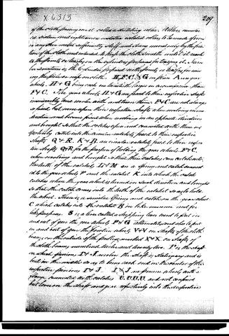
of the cloth passing over it called a notating roller. Rollers number in sixteen and eighteen are metallic notated rollers to be made of iron or any other metal sufficiently stiff and strong merely by the friction of the cloth and intended to keep the cloth smooth until it reach to the points or leagles on the cylinders of the paper factaging it. Same be written in the Cylinder profound notating points or leagles for writing the price or note on cloth. H, F, C, S, G in figure A are gear wheels, H & G being each one toothed larger in circumference than F & C. The gear wheels H & G are fixed to their respective shafts immovably and revolve with and turn them. F & C are not always so fixed but move upon their respective shafts when revolving in one direction and become fixed when revolving in an opposite direction and brought so that the catches upon and connected with them respectively catch into the circular notches fixed to their respective shafts Q & R. K & B are circular notches fixed to their respective shafts Q & R for the purpose of holding the gear wheels F & C when revolving and brought so that their catches can catch into the teeth of the notches L & M on a spring and catch connected to the gear wheel F and the notches K into which the catches catch when the gear wheel is turned in such direction and brought so that the catch comes into the teeth of the notches so as to hold the wheel. There is a similar spring and catch on the gear wheel C which catches into the notches B in like manner and for like purposes. S is a lever called a shifting lever used to put in and out of gear the gear wheels F & G alternately and also to put in and out of gear the friction wheels V & V on shafts of the cloth beams on the outside of the pulleys marked X & X on shafts of the cloth beams numbered twelve and thirteen respectively. P is the shaft on which pinion, D & J, revolve. The shaft is stationary and is bent in the middle so as to bring each end in the centre of the respective pinions D & J. I & J are pinion wheels with a flange connected with notches U, U, U, U, and not confined but loose on the shaft and give respectively into their respective
Page 7.
210. XL313
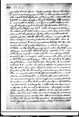
gears which F V G, H V C, D V E are pulleys loose on the shaft P, and moved contrary ways by belts, one being an open and the other a rope belt for the purpose of changing the motion of the cloth. V V V V are dogs which pass through the pulleys D V E respectively by end scoops with them and by means of the shifting lever may be brought so as to be held fast by the catches U U U U on the flanges of the pinions I V J, when it is required to change the motion of the cloth, while a new motion being given to the pinions I V J respectively by being thus connected with the respective pulleys D V E which are always moving with the same velocity in a contrary direction to each other. Lever B, turns on a pivot X and is connected with forks W V W, which are adjusted to the notches of the flanges in which are the dogs V V V V so that the flanges may move while the forks remain stationary and so that the forks being adjusted to the notches of the flanges may by a motion of the lever move the dogs V V V V so as bring them in contact with, or remove them from the catch U U U U as may be required. Lever B extends to the opposite side of the frame, and the end marked O in plan A is connected with rod X X in plan B which is attached to a perpendicular lever Z which turns upon the pivot A A and is made to act by motion of the lever S on a horizontal slide numbered twenty three moving parallel with the opposite side of the frame and the slide numbered twenty three in the plan B is connected with a lever numbered twenty four which is opposite and parallel to lever B and turns on a pivot B B in the centre between the cloth beam numbered twelve and twenty two, so that when lever S is moved it operates on lever numbered twenty four. Twenty five and twenty six in plan B are forks attached to lever numbered twenty four, and lever S, or slide numbered twenty six, and twenty seven in such manner as when lever S is moved in one direction it throws the lay-out or slide numbered twenty seven in contact with dogs 28 and causes the friction pulley V to act on cloth.
Page 8.
210. X6313
gear wheels F & G, H & C, D & E are pulleys loose on the shaft P, and moved contrary ways by belts, one being an open and the other a rope belt for the purpose of changing the motion of the cloth. V, T, T, T are dogs which pass through the pulleys D & E respectively and coincide with them and by means of the shifting lever may be brought so as to be held fast by the catches U, U, U, U on the flanges of the pinions I & J, when it is required to change the motion of the cloth roller, a new motion being given to the pinions I & J respectively by being thus connected with the respective pulleys D & E which are always moving with the same velocity in a contrary direction to each other. Lever S, turns on a pivot X and is connected with forks W & W, which are adjusted to the necks of the flanges in which are the dogs V, T, T, T so that the flanges may coincide while the forks remain stationary and so that the forks being adjusted to the necks of the flanges may by a motion of the lever move the dogs V, T, T, T so as bring them in contact with, or remove them from the catches U, U, U, U as may be required. Lever S, extends to the opposite side of the frame, and the marked O in plan A is connected with rod X, X, in plan B which is attached to a perpendicular lever Z, which turns upon the pivot A, A and is made to act by motion of the lever S on a horizontal slide numbered twenty three running parallel with the opposite side of the frame and the slide numbered twenty three in the plan B is connected with a lever numbered twenty four which is opposite and parallel to lever S and turns on a pivot B, B in the centre between the cloth beam numbered thirteen and twenty two, so that when lever S is moved it operates on lever numbered twenty four. Twenty five and twenty six five in plan B are forks attached to lever numbered twenty four, and bayonet or slide numbered twenty six and twenty seven in such manner as when lever Z is moved in one direction it throws the bayonet or slide numbered twenty seven in contact with dogs 28, one causing the friction pulley V to act on cloth.
Page 9.
time is a combination of motions to have numbered twenty four. The friction pulley V is made to act on the cloth beam numbered twenty two. Also lever B so as to bring the dogs T' T' in contact with the catches on pinion wheel J on the opposite side and the opposite motions will take place both with respect to the gear wheels... rollers and cloth beams. When the machine is in motion and the cloth is passing from the cloth beam numbered twelve under the feeding roller numbered thirteen and so on in the manner before described to the cloth beam numbered twenty two the friction pulley V is acting on the cloth beam numbered twelve for the purpose of preventing the cloth from going off too fast, and the feeding roller numbered twenty moves with a velocity one twentieth part as slow the feeding roller numbered thirteen by reason of the inequality in size of the gear wheels F & G in order to draw the cloth tight and smooth over the cylinder prepared for teasing it and the cloth beam numbered twenty two is moved so as to wind up the cloth by motion communicated from a pulley on the shaft of the feeding roller numbered twenty by means of a belt which will slip so as to accommodate the velocity of the cloth beam to its varying circumstances by means of the winding of the cloth upon it. When the cloth is passing from the cloth beam numbered twenty two under the feeding roller numbered twenty and so on in the manner described to the cloth beam numbered twelve the friction pulley V is acting on the cloth beam numbered twenty two for the purpose of preventing the cloth from going off too fast and the feeding roller numbered thirteen moves with a velocity one twentieth part as slow than the feeding roller numbered twenty by reason of the inequality in size of the gear wheels H & C in order to draw the cloth tight and smooth as aforesaid and the cloth beam numbered twelve is moved so as to wind up the cloth by motion communicated from a pulley on the shaft of the feeding roller numbered thirteen by means of a belt which will slip so as to accommodate the velocity of the cloth beam as aforesaid. It is to be understood incontestably that although I have in my plan and the explanation thereof mentioned a cylinder prepared with grooves or tangles for teasing cloth yet I do not claim as a part of my invention such cylinder either separately or in combination over the teasing of nap on cloth by means thereof and although I have mentioned such
Page 10.
XG 313
219.
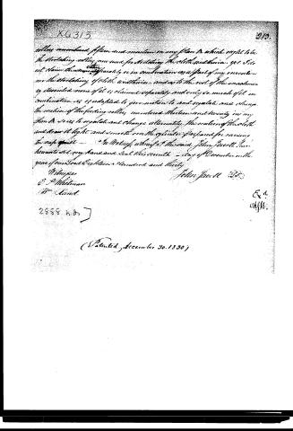
rolls numbered fifteen and motion on my plan A which ought to be the rotating motion now used for rotating the cloth within. yet I do not claim this motion separately, or in combination as a part of my invention nor the rotating of cloth within, and as to the rest of the mechanism as described none of it is claimed separately and only so much of it in combination as is adapted to give motion to and regulate and change the motion of the feeding rolls numbered thirteen and twenty in my plan A so as to regulate and change alternately the motion of the cloth and draw it tight and smooth over the cylinder of paper for receiving the nap cloth.
In Witness whereof the said John Jewell has hereunto set my hand and seal this twenty - day of December in the year of our Lord Eighteen Hundred and thirty.
Witnesses
E. P. Millman
B. A. Aund
John Jewell
2888 n. 8.
(Patented December 30, 1830)
Published accounts: journal notice
Notice in the monthly list of patents (listed with a different spelling or date)
Journal of the Franklin Institute, new ser., vol. 7 (1831), p. 257 · View the page
For a mode of Causing Cloth to pass, and be stretched while passing, over a Revolving Cylinder prepared with points, or teazles, for teazing, or raising, the pile or nap upon cloth; John Jewell, D
About this record
- Patentee
- DATAMP
- Date
- the Name and Date index of patents, DATAMP, USPTO records
- Invention
- DATAMP
- Listed in
- the Name and Date index of patents, DATAMP, USPTO records, Jim Shaw's X-patent list, the Journal of the Franklin Institute, Journal, Burke's List of Patents (1847)
- Also listed in a contemporary journal or list under a different spelling or date; the record shown follows the standard lists.
- Burke's 1847 Patent Office list gives the same patent.