

Drawings and documents
National Archives restored drawings: drawing
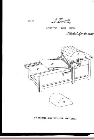
Asa Barrett's Patent Drawing for a Machine for Splitting Cornhusks for Mattresses

National Archives, Restored Patent Drawings (Record Group 241) · Full-size scan at the National Archives · Catalog record
Show the text on the drawing Hide (94 words)
Words on the drawing as machine-read by the National Archives; not checked. Useful mainly for searching.
13. BRAKES GINS. / Hair Pickers / Hos the / ASAL BARRETT / in esplitting cotusksrMattrasses / 96017 / DIVISION / 9601 X / Palented 21 april 1536. / A.B.C. / D. ti Aprons allachento2 "and 3 "Frames / F: upper Filuled Roller / a Rollers with steelpoints miknives / vizepay / / H lever / / Main Cylinder / 70. Styan / to Cepared Pinzon pentings gaving th the Flutend / case Anclosing Main Cylinder / the / Patent office 8th Sept 1838. / Made under the direction of the Description of / Patents in emportunity with act 3 March 1807 / M.L.U.Smoth / of Patent
USPTO scan
The patent as scanned by the USPTO
-
 Page 1
-
 Page 2
-
 Page 3
-
 Page 4


U.S. Patent and Trademark Office · Google Patents
Show the transcription Hide (1,133 words)
Machine transcription (LightOnOCR) of the pages as scanned by the USPTO, most of them the handwritten copies made when the records were restored after the 1836 fire. Not checked; it can misread handwriting, so compare it with the scan.
Page 1.
9601X
A. Barrett,
SPLITTING CORN HUSKS
Patented Apr. 21, 1886.

NO PRINTED SPECIFICATION AVAILABLE.
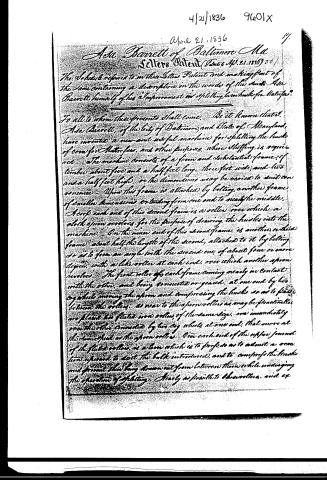
Page 2.
April 21, 1836
Asa Barnett of Baltimore, Md
Sellers Patent (Patent No. 21, 1836)
The Schedule referred to in this Letter Patent and making part of the same containing a description in the words of the Inventor Asa Barnett himself of his "Improvement on Splitting Corn Hushes for Mattoes."
To all to whom these presents shall come, Be it known that I, Asa Barnett, of the city of Baltimore and State of Maryland, have invented a new and useful machine for splitting the husks of corn for Mattoes, and other purposes, where stuffing is required. The machine consists of a firm and substantial frame of timber about five and a half feet long, three feet wide, and two and a half feet high, or the dimensions may be varied to suit convenience. Upon this frame is attached by bolting another frame of smaller dimensions extending from one end to nearly the middle. Across each end of this second frame is a roller over which a cloth apron revolves, for the purpose of drawing the husks into the machine. On the inner end of this second frame is another, or third frame, about half the length of the second, attached to it by bolting so as to form an angle with the second one of about four or more degrees, with a like roller at each end, over which another apron revolves. The first roller of each frame coming nearly in contact with the other, and being connected or geared, at one end by two cog wheels moving the apron and compressing the husks so as to pass between the rollers, as near to the apron rollers as may be practically possible, two fluted iron rollers, of the same size, one immediately round the other connected by two cog wheels at one end, that move at the same speed as the apron rollers. Over each end of the upper journal of the fluted rollers is a bar which is to project so as to admit a motion upward to suit the bulk introduced, and to compress the husks and prevent their being drawn out from between them while undergoing the operation of splitting. Nearly as possible to the rollers, and ex
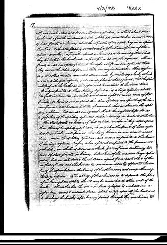
Page 3.
18.
adjacent to each other are two small iron cylinders, or rollers about one inch and a fourth in diameter, into which are inserted two or more rows of steel points or knives, about three-fourths of an inch long in a spiral direction, each row passing around one half the circumference of the cylinder or roller. These steel points or knives are so near together that they will split the husk into as fine fibres as may be required. These points are set one space further to the right or left on one cylinder than they are on the other, to prevent their coming in contact. These cylinders or rollers are also connected at one end, by small cog wheels which revolve with great speed, and are so placed when geared, that the points will perforate the husks at the upper and lower side at the same time.
Nearly as possible to these splitting cylinders, is a large cylinder, about two feet in diameter, in which are driven eight or more rows of flat points or knives, in a spiral direction, of about one-fourth of the circumference, set the same distance from each other as those in the splitting cylinders, but are set one space further to the right or left, so as to pass those of the splitting cylinders without coming in contact with them.
The steel points or knives of this cylinder revolve with greater speed than those of the splitting cylinders, so as to clear the points of these cylinders from husks, and prevent their being thrown over or around round them, under the splitting cylinders, and as near as possible to the knives of the large cylinder. Cooper a bar of wood confined to the frame, on each side, on which is screwed a thick plate of iron containing two rows of steel points or knives, like those of the main or large cylinder, but are set twice the distance apart from each other of those in that cylinder, and the knives in one row are exactly opposite the centres of the space between the knives of the other row, and occupy those of the large cylinder. The utility of these knives is to separate the fibres after having been split, should any be connected at either end of the husk. From this bar the main or large cylinder is enclosed in a light case, except a small space, which is left open at the back end to discharge the husks after having passed through the machine, etc.
Page 4.
one end of the shaft of the large cylinder, is a pulley, around which a belt passes to put the machine in operation. On the same end of the shaft between this first pulley and the cylinder, is another pulley around which a belt passes, and extends around one of very small dimensions, on the shaft of the upper splitting cylinder, giving to those cylinders, a number of revolutions to one of the large cylinder. At the other end of the shaft of this large cylinder is a very small cog wheel or pinion which plays into a cog wheel of five or six times its size. To this large wheel is attached a pinion, which gives motion to a cog wheel of about the size of the former, or large wheel. This last mentioned large wheel, is connected with one of much smaller size, on the end of the shaft of the under fluted roller. This last roller is connected with one of exactly the same size, on the end of the shaft of the upper feeding roller on which the apron revolves giving the feeding and the compressing, or fluted rollers, the same speed, and such speed as is required to feed the machine, and completing the movement of the whole. The husks are first passed by separating them from the stems and throwing out those of poor quality and all hard substances. They are then laid straight and evenly on the apron.
I claim the structure of the machine as above described, as well as the application for the purposes, and use mentioned in this specification.
Witnesses
William Harfield
Samuel Mooryman
Ase Barrell
Patented April 21, 1836
Exp. 4/6.
(11/6 words) (Res't & Renewal new Aug. 21, 1838.)
(Drawing)
Published accounts: journal notice
Notice in the monthly list of patents (listed with a different spelling or date)
Journal of the Franklin Institute, new ser., vol. 18 (1836), p. 71 · View the page
Corn husks, slitting.--Asa Bonett, Baltimore, Md.
About this record
- Patentee
- DATAMP
- Date
- the Name and Date index of patents, DATAMP, USPTO records
- Invention
- DATAMP
- Listed in
- the Name and Date index of patents, DATAMP, USPTO records, Jim Shaw's X-patent list, the Journal of the Franklin Institute, Journal, Burke's List of Patents (1847)
- Also listed in a contemporary journal or list under a different spelling or date; the record shown follows the standard lists.
- Burke's 1847 Patent Office list gives the same patent.