

Drawings and documents
USPTO scan
The patent as scanned by the USPTO
-
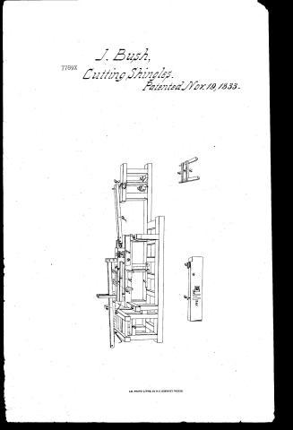 Page 1
-
 Page 2
-
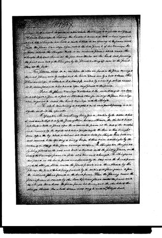 Page 3
-
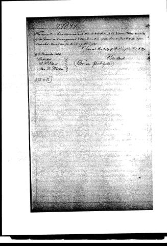 Page 4


U.S. Patent and Trademark Office · Google Patents
Show the transcription Hide (938 words)
Machine transcription (LightOnOCR) of the pages as scanned by the USPTO, most of them the handwritten copies made when the records were restored after the 1836 fire. Not checked; it can misread handwriting, so compare it with the scan.
Page 1.
J. Bush,
7789X Cutting Shingles.
Patented Nov. 19, 1833.
A.M. PHOTO-LITHO. CO. N.Y. (OSBORNE'S PROCESS)
Page 2.
177897
Mar 19 1833
495
John Bush, Dighton, William
Letters Patent
The schedule referred to in this Letters Patent and making part of the same contains a description in the words of the said John Bush himself of his improvements in the machinery for making Shingles.
It is known that John Bush of Dighton, Tiffac, County of William, have made an improvement in the useful arts, being a machine for sawing the blocks or bolts, and cutting, joining, and clamping the Shingles such a Bush Shingle Machine, which is described as follows, reference being had to the annexed drawings, making part of this specification.
This machine consists of the following principal parts:
The frame, containing and supporting the different parts of the machinery; the frame, roller upon which the timber is placed to be cut into blocks or bolts; the saw, with which it is cut the apparatus with which it is raised or split into Shingles; the joining plane with the roll and guides; the hand carriage upon which the Shingles are placed; planes and carriage for clamping or driving the Shingles; the beam for turning the planes; and crank on the main shaft for giving motion to the different parts of the machinery.
The frame is a construction of suitable timber and is adapted by its size, figure, and strength to receive and support the several parts of the machinery to be applied in making Shingles. The front of the frame marked L, upon which the timber is placed upon rollers is erected at one end of the machine.
A long iron bar e, placed on frame A, to give a direction right, making on a bolt is attached to the planing apparatus and works in the axis of the frame, upon which the timber is laid and held down by dogs and cuts it into blocks or bolts for Shingles by the motion of the carriage.
A large or thick spring or fitting the blocks or bolts into Shingles is placed on the side of the plane carriage, and a staff is fastened on the carriage upon which the bolt is placed to be raised.
A joining plane g is also affixed on the side of the frame or carriage.
Page 3.
carriage, and a rack to guide it, upon which the shingles to be jointed are placed. A hand carriage having the handle to move and to hold or bear against which the shingles are laid is made to slide in an opening in the frame and into the plane carriage upon rollers the side piece of this carriage, the means which the shingles rests is an inclined plane which causes the shingles to be cut thinner at the foot and thicker at the head and forming the joint and lock of the shingles by the plane cutting off more at the point than at the butt.
The plane moves in a car before the other one fixed in the plane carriage the front plane moves by ratchet and the hind plane moves by a belt & lever. This plane carriage is attached to a stump, which by a crank, which causes it to move forward & backward upon ways placed in the frame.
Below the plane carriage is attached to the under side of it a lever or working iron in a post or standard therefor raising the plane carriage then, required to insert the hand carriage with the shingle.
The whole machinery is adapted to work each part separately or all together as suits the operator.
Explanation: The machinery being put in motion by the water wheel or one hand shift is by the form of stone driven on thence, the timber & bolt with blocks or bolts is placed upon the rollers on the frame at the end of the machine and secured by the rope and to cut a proper length the stone is then brought down upon the by which is carried into holes or bolts for shingles. These bolts are next removed & the splitting & sizing knife & then main inter-shingles by the motion of the stamp to the plane carriage as before. The shingles are then jointed by being placed on the rail and lock in contact with the joining plane on the side of the carriage frame one side at a time and changed. The shingles on the plane on the hand frame are secured by the bars into the hand frame with the shingle slide under the plane frame and then thrown by the plane so the joint & lock being formed by the motion of the plane frame upon the inclined plane formed on the hand frame. When the planing ceases the plane frame is raised by the lever & the new plane under the frame and the shingle thrown on the plane frame let down, and the other side of the shingle thrown, for a both plane move may be used as a triple beat.
Page 4.
The invention here claimed and desired to be secured by Letters Patent consists of the peculiar arrangement & combination of the several parts of the type writing machine for making things.
Filed at the City of Washington this 8 day of September 1858.
Witnesses:
Wm B. Oliver
Geo W. Walker
J. H. Brush
(Drawn Port Folio)
975 to 75
Published accounts: journal notice
Notice in the monthly list of patents (listed with a different spelling or date)
Journal of the Franklin Institute, new ser., vol. 13 (1834), p. 255 · View the page
For a Machine for Making Shingles; John Bush, Dayton, Tippacanoe county, Indiana, September 19.
DATAMP: illustration
Illustrations from DATAMP
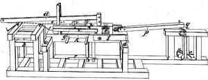
DATAMP (Directory of American Tool and Machinery Patents), via the Internet Archive · Archived DATAMP page
About this record
- Patentee
- DATAMP
- Date
- the Name and Date index of patents, DATAMP, USPTO records
- Invention
- DATAMP
- Listed in
- the Name and Date index of patents, DATAMP, USPTO records, Jim Shaw's X-patent list, the Journal of the Franklin Institute, Journal, Burke's List of Patents (1847)
- Also listed in a contemporary journal or list under a different spelling or date; the record shown follows the standard lists.
- Burke's 1847 Patent Office list gives the same patent.