

Drawings and documents
USPTO scan
The patent as scanned by the USPTO
-
 Page 1
-
 Page 2
-
 Page 3
-
 Page 4
-
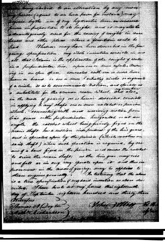 Page 5


U.S. Patent and Trademark Office · Google Patents
Show the transcription Hide (1,022 words)
Machine transcription (LightOnOCR) of the pages as scanned by the USPTO, most of them the handwritten copies made when the records were restored after the 1836 fire. Not checked; it can misread handwriting, so compare it with the scan.
Page 1.
7780X
Sheet 1-2 Sheets.
J. Abbott
Hydraulic Engine,
Patented Nov. 19, 1833.
Page 2.
7780x
Sheet 2 - 2 Sheets
J. Abbott
Hydraulic Engine,
Patented Nov. 19, 1833.

Page 3.
Nov 19, 1833
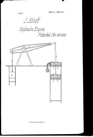
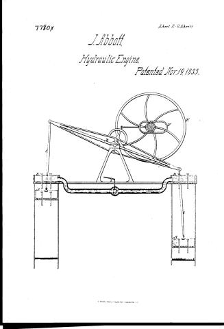
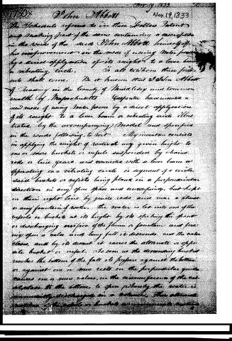
The Schedule refers to in these Letters Patent, and making part of the same containing a description in the words of the said John Abbott himself, of his improvement in the mode of using Water power by a direct application of its weight to a lever beam or vibrating circle. To all to whom these presents shall come. Be it known that I John Abbott of Reading in the County of Middlesex and Commonwealth of Massachusetts Carpenter have invented a new mode of using Water power by a direct application of its weight to a lever beam or vibrating circle illustrated by the accompanying Model and specified in the words following, to wit: My invention consists in applying the weight of water at any given height to one or more buckets or vessels suspended by chains, rods or line yarns and connected with a lever beam or operating on a vibrating circle or segment of a circle, said buckets or vessels being placed in a perpendicular direction in any open space and unobstructing, but kept on their right line by guide rods and near a stream or any fountain of water. The water is let into one of the vessels or buckets at its height by its striking the spout or discharging orifice of the stream or fountain and flowing upon a valve and being full it descends, and the valve closes, and by its descent it raises the alternate or opposite bucket or vessel. As soon as the descending bucket reaches the bottom of the fall its pressure against the bottom or against one or more rests on the perpendicular guide causes one or more valves, in the circumference of the vessel close to the bottom, to open whereby the water is immediately discharged on a platform. Then alternate positions of the buckets or vessels are commenced again.
Page 4.
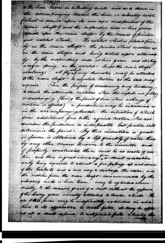
to the lever beam or vibrating circle and as is shown in the accompanying model, the lever or vibrating circle (which is moved upon its own axis independent of the main shaft) and the suspending rods or line gears operate upon the main shaft by the means of pinion and ratchet wheels. The ratchet wheel is placed firmly on the main shaft, the pinion wheel revolves upon the same shaft and being acted upon alternately by the suspending rods or line gears, and striking a cog or spring on the ratchet, keeps the main shaft revolving. A fly wheel of any diameter may be attached to the main shaft to regulate motion as the case may require. For the purpose of overcoming any tendency to check the alternate motion when the wheels are filling or discharging (being the point of time when a change of motion is effected) a pendulum may be introduced as in the accompanying model, the vibration of which gives additional force to the required motion. I do not consider the pendulum as indispensable but practice will determine the point. By this invention a great or power is obtained by a life quantity of water than by any other means known to the inventor and if properly constructed there need be no waste of water, and there is great economy, a small expenditure only being required to admit a free passage up and down of the buckets and a race way to discharge the water, and the motion from the main shaft communicated by the vibrating circle or lever beam, may be extended immediately to the running gears of a mill without the expense of the heavy gears usually attached to water wheels. The use of this power may be indefinitely extended in addition to its application to water falls, it may be applied as at a small expense to artificial falls whereby the
Page 5.
being raised to an elevation, by any moving piston (equal to an horse power for instance) may be raised by the use of my hydraulic lever, as measured power in proportion to its height, and it may also be advantageously used for the raising of weights in water houses and other places where a fountain would be had.
Machines may have been described in the foregoing specification. My whole invention consists, in, and all that I claim is the application of the weight of water in a perpendicular line, upon one or more wheels, moving in an open space, connected with one or more lever beams or beams or one or more vibrating circles or segments of a circle, so as to communicate motion, and operate as a substitute for the common water wheel, and also, in the mode of gearing as is herein described, consists in applying to any shaft one or more ratchet or pinion wheels, connecting with and receiving motion from line gears either perpendicular, horizontal or at an angle, the ratchet wheel being firmly fixed on the main shaft has a motion independent of the line gears, and is operated upon by the pinion (which revolves on said shaft) when such operation is required, by means of a band fixed on the pinion, and causes the ratchet to drive the main shaft, as the line gear may rise and fall or in any way operate upon it and this improvement in the mode of gearing, may be applied to steam engines generally.
In testimony that the above is a true specification of my said invention as above described, I have here set my hand this eighteenth day of September eighteen hundred and thirty-three.
Witnesses
Thomas O. Day
Wm. H. Dickinson
John H. H. 32d of Dec
Published accounts: journal notice
Notice in the monthly list of patents (listed with a different spelling or date)
Journal of the Franklin Institute, new ser., vol. 13 (1834), p. 254 · View the page
For an improvement in the Mode of using Water Power; John Abbott, Reading, Middlesex county, Massachusetts, September 19.
About this record
- Patentee
- DATAMP
- Date
- the Name and Date index of patents, DATAMP, USPTO records
- Invention
- DATAMP
- Listed in
- the Name and Date index of patents, DATAMP, USPTO records, Jim Shaw's X-patent list, the Journal of the Franklin Institute, Journal, Burke's List of Patents (1847)
- Also listed in a contemporary journal or list under a different spelling or date; the record shown follows the standard lists.
- Burke's 1847 Patent Office list gives the same patent.