

Drawings and documents
National Archives restored drawings: drawing
James McClory's Patent Drawing for a Door Lock

National Archives, Restored Patent Drawings (Record Group 241) · Full-size scan at the National Archives · Catalog record
Show the text on the drawing Hide (76 words)
Words on the drawing as machine-read by the National Archives; not checked. Useful mainly for searching.
vol. 26 page 221 Histore Patent, / 70. / 70. LOCK3 & LAICHEN / / Looks, / Tumble / Recorded in bol. 26 Page 221 Restored Patents / Seche- / #2= / CLASSI / 9511 X / JAMES M° CLORY'S / DIVISION. / 9511 X / Door Lock / patented 18th March 1836. / Lumbles located undermath the balt / betand a luating / (c / as / to / to / I' / G, V / I' / termbles to / moved / sideving / R. / continance / to / the / la / G.S.Dez" / IAM / 12th
USPTO scan
The patent as scanned by the USPTO
-
 Page 1
-
 Page 2
-
 Page 3
-
 Page 4


U.S. Patent and Trademark Office · Google Patents
Show the transcription Hide (1,156 words)
Machine transcription (LightOnOCR) of the pages as scanned by the USPTO, most of them the handwritten copies made when the records were restored after the 1836 fire. Not checked; it can misread handwriting, so compare it with the scan.
Page 1.
No Printed Specification Available
9511X
J. McClory,
Lock.
Patented Mar. 18, 1836.
AM. PHOTO-LITHO. CO. N.Y. (OSBORNE'S PROCESS)
Page 2.
Jan. 15
Filed 181836
221.
X9511
James Mc Cleary City N.Y.
Letters Patent
The following referred to in the Letters Patent and making part of the same containing a description in the words of the said James Mc Cleary himself of his improvement in the Door Lock.
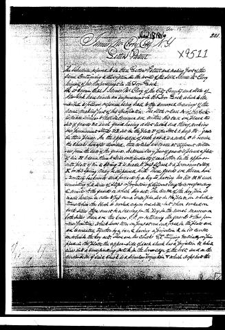
It is known that I James Mc Cleary of the City County and State of New York have made an improvement in the Door Lock which I have made a follow reference being held to the annexed drawings of the same making part of this specification. The stock or Case A of this lock is made similar to that in common use. Within the case are placed the set of gears Bc each gear having a slot in each end therefor working on permanent studs DB set in the plate E of the stock to keep the gears in their places. In the upper edge of each gear is a notch C to receive the cheeks hereafter described. The notches are made at different distances from the ends of the gears. Between every pair of gears is placed a plate of the F to cause them to slide and prevent any of each other. On the upper or inner plate of the A spring I is made to pass against a permanent stud K on this spring may be dispensed with. These gears are thrown here and there backwards and forwards by a key L having two bits MN each consisting of a series of steps or projections of different lengths corresponding to number of the gears in which they act. The centre of the key pin is made hollow in order to pass over a similar piece set in the plate on which it turns when the lock is worked in one direction but when turned over to the other side there must be a key for the key in the usual manner on both sides. There are two bars O P for returning the gears to their former positions. A lock lever turns on pins at one end and pivots in the plate and are connected together by a bar Q having a projection R in its centre on which the key acts. There are two cheeks S T turning vertically on pins fixed in the plate; the upper slide of each cheek has a projection U which slides into a corresponding notch in the lower edge of the lock and on the under side of said cheek is a similar projection V which slides into the
Page 3.
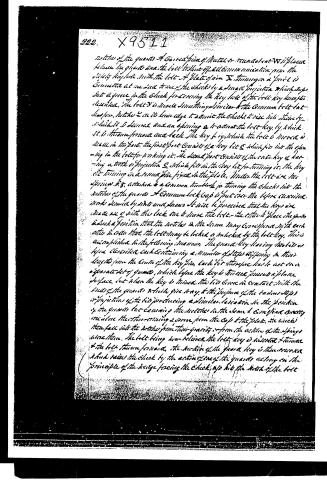
notches of the guards A. A curved piece of Metal or round sheet W is placed between the guards and the bolt to shut off all communication from the sliding key hole. With the bolt A plate of iron X. Turning a pin is connected at one end to one of the cheeks by a small projection which drops into a groove in the cheek for covering the key hole of the bolt key has just described. The bolt Y is made something similar to the common bolt but has two notches 2 on its lower edge to admit the cheeks to rise like stairs by which it is drawn and an opening 3 to admit the bolt key by which it is thrown forward and back. The key by which the bolt is moved is made in two parts. The first part consists of a key bit 5 which fits into the opening in the bolt for locking it. The second part consists of the enter key 4 having a tooth or projection 6 which fits in the key bit for turning it. The key bit turning in a round piece fixed in the plate. Under the bolt are two springs 8, 8, attached to a common turnbuckle for turning the cheeks into the notches of the guards. A Common lock Cap is put over the before described work secured by a nut and screws. It will be perceived that the keys are made one of with the lock one to move the bolt. The other to place the guards in such a position that the notches in the same may correspond with each other in order that the bolt may be locked or unlocked by the bolt key. This is accomplished in the following manner. The guard key having two bits as before described, each containing a number of steps differing in their lengths from the centre of the key pin, each bit therefore has to act on a separate set of guards, which before the key is turned present a plane surface, but when the key is turned the bits come in contact with the ends of the guards which give way, and the purpose of the various steps or projections of the bits producing a similar variation in the position of the guards but causing the notches in the same to correspond exactly one with the other, turning a screw from the Cap to the plate, the cheeks then fall into the notches from their gravity or from the action of the springs above them. The bolt being now raised the bolt key is inserted & turned & the bolt thrown forward. The motion of the guard key is then reversed which raises the cheek by the action of one of the guards acting on the principle of the hinge forcing the cheek up into the notch of the bolt.
Page 4.
and thus secure it. It must be observed that in turning the guard key the flat side of the guard key passes the key hole of the bolt to remove one that, when the bolt is withdrawn on the motion of the guard key, remove that side plate again returns to its former position in the key hole and effectually secures it from the introduction of picks or other implements. By thus having the guard of an uniform length and presenting an even and plain surface the possibility of taking an impression for the purpose of making a false key is effectually prevented. And besides the before described construction the door lock is rendered much cheaper, more durable and less liable to be picked than any lock known. All that I claim as new and is my invention in the before described lock and in which I ask a patent are the guard, the plates, the flange between them, the cheeks, the lugs and bar, the application of the double fitted key to this lock and the mode of operating the same, just as before described.
Witnesses
John P. Elliot
Thomas Lloyd
James McCary
1170
Drawn
Published accounts: journal notice
Notice in the monthly list of patents
Journal of the Franklin Institute, new ser., vol. 17 (1836), p. 438 · View the page
211. Door lock.-James McClory, N. York,
Published accounts: journal notice
Notice in the monthly list of patents, with remarks
Journal of the Franklin Institute, new ser., vol. 18 (1836), p. 390 · View the page
71. For a Door Lock; James M'Clory, City of New York, March 18.
Remarks. The claim made is, to "the guards, the plates of tin placed between them; the levers and bar; the application of a double bitted key to this lock, and the mode of operating the several parts." The drawing gives a very imperfect representation of this lock, and the claims extend to things which have no novelty when taken individually, as is done in the foregoing summary. The guard, are flat plates of metal laying upon each other, and operated upon by the key; the cam, or bit, of which is in steps, so as to push the plates to different distances, in disengaging the bolt. Double bitted keys have been frequently used; the mode of operation in some of the parts is new, but this is not the case generally. The lock is probably a very good one, and we believe that it has sufficient novelty to admit of a sustainable claim.
About this record
- Patentee
- DATAMP
- Date
- the Name and Date index of patents, DATAMP, USPTO records
- Invention
- DATAMP
- Listed in
- the Name and Date index of patents, DATAMP, USPTO records, Jim Shaw's X-patent list, the Journal of the Franklin Institute, Burke's List of Patents (1847)
- Burke's 1847 Patent Office list gives the same patent.