

Drawings and documents
National Archives restored drawings: drawing
John Holton's Patent Drawing for a Platform Balance

National Archives, Restored Patent Drawings (Record Group 241) · Full-size scan at the National Archives · Catalog record
Show the text on the drawing Hide (45 words)
Words on the drawing as machine-read by the National Archives; not checked. Useful mainly for searching.
6250 / Platform Balance. / CI ASSITICATION / 9878.4 / Patented July / DIVISION / 9878 X / Fig 1 / Scale for Fig: 1,2 53 = 2 Inches to the Foot. / Fig 2. / F) / HE / I OF / Fig4 / Fig5. / Fig7. / Fig 8. / Fig6. / Fig3. / Fig.9. / Fig10.
USPTO scan
The patent as scanned by the USPTO
-
 Page 1
-
 Page 2
-
 Page 3
-
 Page 4
-
 Page 5
-
 Page 6


U.S. Patent and Trademark Office · Google Patents
Show the transcription Hide (1,860 words)
Machine transcription (LightOnOCR) of the pages as scanned by the USPTO, most of them the handwritten copies made when the records were restored after the 1836 fire. Not checked; it can misread handwriting, so compare it with the scan.
Page 1.
9878X
J. HORTON.
PLATFORM BALANCE.
Patented July 2, 1836.
Fig. 1.
Fig. 2.
Fig. 3.
Fig. 4.
Fig. 5.
Fig. 6.
Fig. 7.
Fig. 8.
Fig. 9.
Fig. 10.
Page 2.
July 2, 1836
John Horton, Maitland & Co.
Sellers Patent
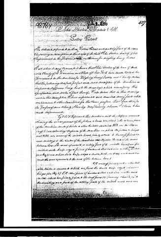
The schedule referred to in these Sellers Patent and making part of the same containing a description of the mode of the said John Horton himself of his improvement in the platform scales or balances for weighing heavy bodies.
We all where it may concern, be it known that John Horton of the town of Maitland County of St. Lawrence and State of New York have made certain improvements in the machine for weighing heavy bodies, and hereby declare that the following is a full, perfect and exact description of the machine as improved, reference being had to the drawings which accompany this specification, and make a part thereof. We also declare that in these drawings and in this description we have represented and described many parts which are common to other machines for the same purpose, these have been for the purpose of more clearly showing, describing, wherein we claim to have made improvements.
Fig 1 represents the machine with the platform removed showing the arrangement of the fulcrum, levers, etc., etc. 1 is the balance frame of the machine, made of iron or other suitable material. A, B, C, D, E, F, G, H, I, J, K, L, M, N, O, P, Q, R, S, T, U, V, W, X, Y, Z are arms of the middle levers, firmly attached to the cross pieces, etc., and meeting in the center of the machine directly over the end of the main balance beam. The arms of said, or acting parts of the middle levers are furnished with knife edged pieces of hardened steel cast iron or other metal (as in Fig 1) one or both sides, knife edges a center block, etc. (as in Fig 2) are to and connect the arms of said to the end of the balance beam.
B, C are cross pieces of iron or other suitable material, or material which are fixed the middle knife edged pieces or hinges (as in Fig 1). E, F are pieces of hardened steel cast iron or other metal, which are firmly fixed to the cross pieces, etc., forming there by said the receiving and part of the acting parts of the middle levers and are
Page 3.
138. 98787
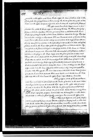
furnished with upper and lower knife edges, the lower of which rests in the plate of the swinging fulcrum or bail forming the centre of the line of the middle beam and the upper assigned to receive and sustain the weight of the platform.
The upper and lower knife edges are on a horizontal beam with the knife edge on the side of the beam O, A, and swinging fulcrum or bail having some distance given a plate in which to set the lower knife edge of that part of the middle beam, said plate described having knife edge on each side, resting on standards A, B, and standards made of hardwood steel cast iron or other hard metal, resting on and fixed to the cross pieces I, K, and having base plates or scales on the top with guards on the outer side which form fulcrum in which the knife edges of the swinging fulcrum or bail to rest (See Fig 2 and 3 to the plate) which give a swinging motion to the beams and cause the beams to accommodate themselves to the rise and fall of the platform without friction or scraping in the knife edges. I, K, are pieces of hardwood steel cast iron or other hard metal, which are fastened to the acting ends of the beams having knife edges to which are set the connecting hooks I, K, a beam of oak or other suitable wood having knife edged pieces L, M, fastened to each of its ends a hook is situated to the exterior end of this beam, a lever working over the knife edge which is on the lower side from which a connecting rod of wrought iron reaches to the steel guards. The inner end is connected to the centre beam by means of a double lock which fits with the inner and outside and works over the lower knife edge M on the lower end and the upper knife edges N, O, on beam, P, Q.
It is a yardarm, made of hardwood steel or cast iron and is fixed into and joins the centre of motion in the main platform beam & equidistant from its ends with knife edges on the upper side of each of its ends & rock in the bar pieces R, S, & T, the bar pieces of hardwood steel cast iron or other hard metal, which are fixed to the hinges C, C, C, forming fulcrum in the knife edges of the yardarm & rock, S, S, are hinges of pine or other timber, steel, cast iron or otherwise fixed together forming a key around the apparatus.
Figures 3, 4 represent the under side of the platform which are parts of the frame work, A, B, C, D, are cross pieces, made of oak or other hard metal, hinges C, C, C, C, are pieces of hardwood steel, cast iron or other hard metal, having grooves of plates with guards on the outer side which form fulcrum to which
Page 4.
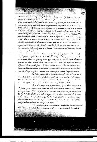
the knife edge, resting on the movable leverstock. Fig 1 is a view, part of what is called the Deadman Plate, as improved by me and adapted to my platform balances. It is made in the usual way of steel, and is fitted with a movable piece with notches and figures in the bar, but at the end is inserted a piece through the bar with knife edges on the upper side of each inch, over which a small hook plays to which the Spring Cd is attached by means of a hook for the reception of weights. E. is a smooth round rod of iron, attached to the end of the steel yard bar on which the ball A slips. B is a ball of iron prepared with a hole of the size of the rod, C, on which it slips with a thumb screw inserted through the side of the center of the ball and which fastens the ball when required to the rod. The object has in view by the use of the rod and ball when attached to the steel yard is to form a counterpoise to the platform (preparatory to weighing).
Common scales (weights bearing a given ratio to each other are prepared to be placed in the slot Cd. The steel yard being graduated with the movable piece to weigh any number of pounds from one to a hundred. The weights placed in the slot Cd may denote 100, 50, 25, 10, 5, 2, 1, or any other number of pounds. The movable piece will point out the number of pounds between the hundreds. These numbers are given only to explain the principle and to effectuate a weight of any required amount and may be graduated to any size desired.
Fig 6 is a perspective representation of the movable knife edge lever Cd, the lower knife edge of which forms the center of motion of the movable lever and works the swinging fulcrum or bail. The upper lever is in the fulcrum, as Fig 6 and carries and sustains the weight of the platform.
Fig 6 is a perspective representation of the knife edges A, H.
Fig 7 is a representation of the steel hook which connects the levers in the center of the machine.
Fig 8 is a perspective representation of the car fulcrum or platform.
Fig 9 is a perspective view of the swinging fulcrum or bail showing the manner in which they rest on the standards.
Fig 10 is a perspective representation of one of the standards showing the base plate or stock to which the knife edge of the swinging bail or fulcrum are designed to rest.
The construction of a machine for weighing loaded wagons is nearly identical in such a manner in the arrangement of the lever and the
Page 5.
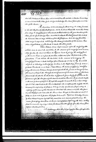
that the balance or lever lever which arms from the middle, or center lever may be carried out to the limits by so doing, retaining the same principles and action of the levers.
The machine as constructed for show may be either portable or let into the floor so that the platform will be level therewith and the balance lever may be lengthened or shortened without altering the graduation of the steel yard by so doing I am enabled to attach the steel yard to the ends of the balance lever at any distance from the platform and in any position that may be required retaining the same graduation of the balance lever when lengthened or shortened to reach the steel yard.
I also claim as an improvement upon the weighing machine, now in use is the variation in the manner of arranging and connecting together the levers as shown in Figures 1 and 2 giving the acting part of the Centrifugal or a power Machine which are upon the first order of lever purchase. I also claim the variation in the manner of arranging the weighing factors or facts resting upon standards as seen in Fig 2 which supports a vibratory or swinging motion in the supporting force by means of said standards more easily. I also claim the manner of fixing and placing the movable balance lever by means of which the power is conveyed from the Centrifugal lever to the steel yard rod by means of its connection to the center lever with the centric hook as seen in figures 2. (form in fig 1). I claim an improvement upon the steel yard by the manner in which I combine the graduated weight at the end by means of the pin through the end of the bar and the hook, or bar resting upon its knife edge to which the steel is attached for the reception of the weight also the manner of connecting the platform to bring it into equilibrium proper as to weighing by the means of the smooth rod attached to the extremities of the steel yard bar, and the perpendicular ball with the tension lever through its stem which is made to slide on said rod to produce the proper balance (See Fig 4) not intending however by these claims to confine myself to the exact form and manner of constructing the various parts of my machine as herein exemplified but to cover the same acting said Centrifugal in any way which produces similar effects upon the same principles or modes of action.
In testimony that the foregoing is a true specification
Page 6.
of my said improvement as herein before stated, I have hereunto set my hand this nineteenth day of October in the year of our Lord one thousand eight hundred and thirty five.
Witnesses:
Chas. Schickel
Mrs. Philpott
Drawing
Published accounts: journal notice
Notice in the monthly list of patents
Journal of the Franklin Institute, new ser., vol. 18 (1836), p. 359 · View the page
581. Platform balance. John Horton, Madrid, N. Y.
About this record
- Patentee
- the Journal of the Franklin Institute, Journal
- Date
- the Name and Date index of patents, USPTO records, Jim Shaw's X-patent list
- Invention
- the Name and Date index of patents
- Listed in
- the Name and Date index of patents, USPTO records, Jim Shaw's X-patent list, the Journal of the Franklin Institute, Burke's List of Patents (1847)
- The patentee's full name comes from the Franklin Institute's journal.
- Burke's 1847 Patent Office list gives the same patent.