

Drawings and documents
National Archives restored drawings: drawing
Robert l. Thomas' Patent Drawing for a Rotary Saw

National Archives, Restored Patent Drawings (Record Group 241) · Full-size scan at the National Archives · Catalog record
Show the text on the drawing Hide (59 words)
Words on the drawing as machine-read by the National Archives; not checked. Useful mainly for searching.
263 WOOD-SAWING / Saw-Teoth / Secretary / 50 $ / Shober / CLASSTA 156 TIEN / 9.84% t / DIV inticration / Rotury San. / 9847X / Patented Truly 1836. / Vol. 27. 1453 / Fo / Frg 2 / OD / DO / of / DO / Do / oD / F° / op / o D / oD / Plate with gap / M MK / Top vierv of plate sco / M L M / chisel 5 shank
USPTO scan
The patent as scanned by the USPTO
-
 Page 1
-
 Page 2
-
 Page 3
-
 Page 4


U.S. Patent and Trademark Office · Google Patents
Show the transcription Hide (949 words)
Machine transcription (LightOnOCR) of the pages as scanned by the USPTO, most of them the handwritten copies made when the records were restored after the 1836 fire. Not checked; it can misread handwriting, so compare it with the scan.
Page 1.
9847X
R. S. THOMAS.
Rotary Saw.
Patented July 1, 1836.
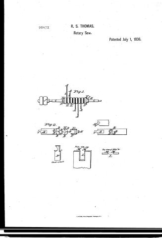
Fig. 1.
Fig. 2.
Chisel & Shank
Plate with gap
Top view of plate &
N. PETERS, Photo-Lithographer, Washington, D. C.
Page 2.
7/1/1836 9847X
July 1, 1836 453
Robert Sands Thomas of Rockingham, North Carolina
Setting Patent
The schedule referred to in these Letters Patent and making part
of the same containing a description in the words of the said
Robert Sands Thomas himself of his “Improvement in the
manner of constructing the Rotary Saw”
To all to whom these presents shall come, Be it known that
I Robert Sands Thomas of Rockingham in the County of
Richmond and State of North Carolina have invented a new
and useful improvement in the manner of constructing a rotary
saw, and I do hereby declare, the nature of my said invention
and the manner in which the same is to be performed, as be-
ing fully described and ascertained in and by the drawing
hereto annexed, and the following description thereof, that
is to say: The invention consists in attaching to a revolving
shaft several plates of metal by an opening in one end there
of fitting them to said shaft, while at the other end will be
secured in a manner to be described hereafter a chisel shaped
tooth, which will be made movable for the purpose of repair
&c. They will be placed at required distances around, and
so arranged around the shaft as to form a continuation of plates
and teeth in a spiral direction, thereby forming as many dif-
ferent saws revolving in a circle the radius of which will
be the distance between the centre of the shaft and the point
of the tooth formed by the length of the plate. That my in-
vention may be better understood I will now describe the
drawing hereto annexed and the figures and letters marked
thereon, that is to say
Description of the Drawing.
Fig 1 is an elevation or side view of a shaft, and its saws.
at plates constituting a gang of toothed saws, placed at prop.
Page 3.
7/11/1836 9847x
154.
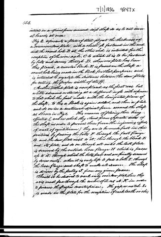
intervals in a spiral form around said shaft so as to cut several boards at once.
Fig 2. represents a plate of steel about the thickness of a common saw plate, with a chisel A fastened in the end, and the round hole B at the other end is intended for the reception of the iron axle C to which it is to be fastened by bolts and screws through D. When one plate has been thus placed, a circular block E is passed on the shaft a round hole being made in the block for that purpose, and is intended to regulate the distance between the saw plates for cutting the proper width of stuff.
Another toothed plate is now placed as the first was, but a little advanced or standing at a different angle with reference to that which the first made with the horizontal plane of the shaft, to this a block is again added, and then a plate and so on in a continued spiral form around the shaft as shown in Fig 3. This manner of placing them being effected C and in which they stand from opposite sides of the shaft in order to prevent them from the injurious effects of want of equilibrium) they are to be made fast in their positions by passing the bolts F through the fast flange G and the saw plate next to it, then through the block E and its plate, and so on through all until the last plate is secured by the outside loose flange H which is passed up to it, through which the bolts pass and are finally secured by screw nuts. When it is only left to pass a bolt I through the loose flange and shaft to make all secure. The shaft is driven by the pulley J from any given power.
Should it be desired to work only one saw plate, then the axis must pass through the centre of it, as at K in order to preserve the proper counterpoise. The gap or notch L is made in the plate for the reception of each tooth or chis
Page 4.
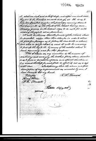
cl. about one inch and a half deep, and about one inch wide, they are to be bevelled on each side as at M, so as to have two parallel angular shaped edges running down to their base. N is the shank of the chisel having corresponding grooves in the lateral edges O so as to fit with accuracy the gaps so above described.
It will be obvious that the points of the chisels should be somewhat under than their shanks, in order to allow the plate free passage as it follows the saw tooth or chisel, and when a single chisel is used it will be necessary to feed up the log to it, by means of the sashet wheel & hand commonly used for the purpose.
What I claim as my invention is the manner of combining and arranging the toothed plates above described so as to form a succession of saws in a spiral direction or line around the shaft for each plate to effect its cut as a separate saw.
In testimony that the above is a full description of my improvement as invented by me, I have hereunto set my hand.
Witnesses
Henry Stone
B. H. Morell
R. S. Thomas.
(Patented 12th July 1836)
Published accounts: journal notice
Notice in the monthly list of patents
Journal of the Franklin Institute, new ser., vol. 18 (1836), p. 359 · View the page
597. Neck stocks, shaping.-Thomas Goodman, N. Y.
DATAMP: illustration
Illustrations from DATAMP


DATAMP (Directory of American Tool and Machinery Patents), via the Internet Archive · Archived DATAMP page
About this record
- Patentee
- DATAMP
- Date
- the Name and Date index of patents, DATAMP, USPTO records
- Invention
- DATAMP
- Listed in
- the Name and Date index of patents, DATAMP, USPTO records, Jim Shaw's X-patent list, the Journal of the Franklin Institute, Burke's List of Patents (1847)
- Burke's 1847 Patent Office list gives the same patent.